


- Products
- Catalogs
- News & Trends
- Exhibitions
253P Series

253P Series
- High temperature resistance up to +200°C.
- Ultra-stable performance across temperature and voltage ranges.
- Rugged and lightweight construction.
- Manufactured in the U.S.
- Oil & Gas industry.
- Aerospace & Defense sectors.
- High temperature modules.
- Construction: Non-inductive wound PTFE metallized polymer film.
- Case: Flame retardant tape wrap with high temperature resin end fill.
- Lead Material: PTFE insulated silver stranded copper wire for <600 V, MIL-W-16878/4 (Type E) wire for >600 V.
- Lead Strength: Can withstand a five-pound pull force on lead axis.
Example: 253P 105 X9 050, where 253P is the series, 105 is the capacitance code (1 µF), X9 is the tolerance code (±10%), and 050 is the voltage rating (50 VDC).
- Operating Temperature: –55°C to +200°C without derating for DC operation.
- Capacitance Range: 0.022 µF to 1.0 µF.
- Capacitance Tolerance: ±10%, ±5%.
- Dissipation Factor: 0.05% max at 1 kHz @ 25°C.
- Insulation Resistance: Varies with temperature, from 1,000,000 MΩ-µF at +25°C to 2,000 MΩ-µF at +200°C.
Wrap-and-Fill High Temperature PTFE Film capacitors 253P Series with various dimensions and lead wire sizes depending on the case diameter.
Includes configuration outline and dimensions in inches for different capacitance values and voltage ratings (250 VDC, 400 VDC, 600 VDC, 800 VDC).
- Change in Capacitance vs Temperature: Shows percentage change in capacitance from -50°C to +200°C.
- Dissipation Factor vs Temperature: Displays dissipation factor percentage from -50°C to +200°C.
- Change in Insulation Resistance vs Temperature: Illustrates insulation resistance in MΩ-µF from 25°C to 200°C.
Custom configurations and extended/intermediary values are available upon request.
Catalog excerpts

FILM CAPACITORS Taping : dimensions 253P Series Wrap-and-Fill High Temperature PTFE Film capacitors Film Capacitor with PTFE Dielectric Industry-Leading Performance at Temperatures up to 200°C ELECTRICAL SPECIFICATIONS • High temperature to +200°C • Ultra-Stable Performance through Electrical specifications Parameter Temperature/Voltage Range • Rugged/Lightweight Construction • Manufactured in U.S. Operating Temperature Capacitance Range Capacitance Tolerance Dissipation Factor • Oil & Gas • Aerospace & Defense • High Temperature Modules PHYSICAL CHARACTERISTICS Construction: Non-Inductive wound PTFE metallized Polymer film Case: Value –55°C to +200°C Without derating for DC operation 0.022 µF to 1.0 µF ±10%, ±5% 0.05% max When measured at 1 kHz @ 25°C 1,000,000 MΩ-µF, need not exceed 2,000,000 MΩ 200,000 MΩ-µF, need not exceed 400,000 MΩ 25,000 MΩ-µF, need not exceed 50,000 MΩ 2,000 MΩ-µF, need not exceed 4,000 MΩ Custom configurations and extended/intermediary values available upon request. Flame retardant tape wrap and high temperature resin end fill Lead Material: < 600 V PTFE insulated silver stranded copper wire > 600 V MIL-W-16878/4 (Type E) wire Lead Strength: Capable of withstanding a five pound pull force on lead axis Capacitance code Tolerance code Voltage rating
Open the catalog to page 1
FILM CAPACITORS General characteristics 253P Series Wrap-and-Fill High Temperature PTFE Film capacitors OUTLINE DIMENSIONS in inches Lead Wire Sizes Case Diameter Lead AWG 0.301 to 0.500 No. 22 > 0.500 No. 20 x 1.750 * Leads to be within ±0.062”at center line at egress, but not less than 0.031” from edge DIELECTRIC CHARACTERISTICS CONFIGURATION OUTLINE Change in Capacitance vs Temperature Dissipation Factor vs Temperature 0.10 Dissipation Factor (%) Change in IR vs Temperature Insulation Resistance (MΩ-µF) * Input tolerance number to complete part number: 9 = ±10%, 5 = ±5% Custom configurations...
Open the catalog to page 2All EXXELIA catalogs and technical brochures
 PHM 912
5 Pages
 FELSIC HC
17 Pages
 DSCC 10004
2 Pages
 CUBISIC SLP
3 Pages
 560P Series
2 Pages
 Tantalum Capacitors Product Catalog
140 Pages
 Ceramic Capacitors Catalog
148 Pages
 Broadband Series
8 Pages
 CF/CFS Series
8 Pages
 FILM& MICA Capacitors Catalog
132 Pages
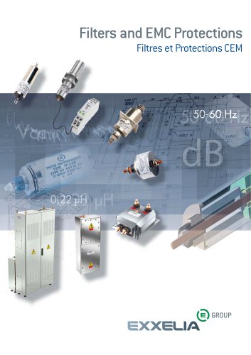 Filters and EMC Protections
84 Pages
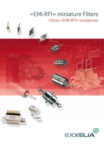 EMI-RFI Filters Catalog
82 Pages
 Wound Magnetics Technologies Catalog
123 Pages
 Microwave Components Catalog
204 Pages
 Product & Solutions Catalog
16 Pages
 Electrolytic Aluminium Catalog
124 Pages


- Transformer
- Angular encoder
- Dry transformer
- Electrical rotary joint
- Absolute rotary encoder
- Position transducer
- Encapsulated transformer
- Power transformer
- Optical rotary encoder
- Electronic filter
- Linear position transmitter
- Industrial transformer
- Three-phase transformer
- Passive electronic filter
- Electric electrical rotary joint
- AC electronic filter
- Ceramic capacitor
- Compact electrical rotary joint
- Low-pass electronic filter