
- Catalogs
- Exergen Global
- IRt/c.2ACF Base Model

IRt/c.2ACF Base Model

IRt/c.2ACF Base Model
The IRt/c.2ACF is an infrared thermocouple sensor designed for non-contact temperature measurement. It is self-powered, intrinsically safe, and offers high repeatability and interchangeability. The sensor is suitable for both high emissivity (non-metal) and low emissivity (metal) surfaces.
- Sensing Range: 500 to 2500°F (260 to 1370°C) for non-metals; 1000 to 2500°F (540 to 1370°C) for metals.
- Minimum Spot Size: 0.11” (2.9 mm) at 1.7” (43 mm) from the sensor.
- Field-of-View: Approximately 30° for non-focus applications.
- Spectral Response: 2 to 20 μ for non-metals; 0.1 to 5 μ for metals.
- Output Impedance: 4 to 8 Kohms, varying by model.
- Cable: Twisted shielded pair, 3 ft (0.9 m) standard length, Teflon sheathed.
- Dimensions: 2.02” x 1.375” Dia. (51.3 x 35 mm).
- Weight: 6.8 oz (192 g) with cable.
- Housing: Stainless steel, hermetically sealed, exceeds NEMA 4,4x; IP65,67.
- Air Purge: Built-in, with cooling capacity to 400°F (200°C) ambient.
- Connect air purge if the process is already at operating temperature, ensuring a minimum of 5 psig (30 kPa) air pressure.
- Install the IRt/c sensor and align it to view the target. Connect leads to the readout device.
- If the target temperature is unknown, measure it with a reference. Adjust the calibration screw to obtain the desired reading.
- Replace the setscrew cover after calibration. Use ZERO or OFFSET adjustments on readout devices for final process adjustments.
For maximizing the linear range, refer to Tech Note #70. The calibration screw functions like a radio volume control, increasing the signal when turned clockwise.
Catalog excerpts

Infrared Temperature Sensors Product Overview • Infrared Thermocouple IRt/c • Self Powered • Intrinsically Safe • Close Focus Range Adjustment Screw " #10-32 MOUNTING HOLES ON A 1.0" (25,4) DIA BOLT CIR-. MOUNTING SCREWS PROVIDED plane. Spot size increases with included angle away from focal Technical Data Set-up and calibration instructions For all IRt/c Models with "A" in model designation (IRt/c.xxxA) 1. Connect air purge first if installing in process already at operating temperature. Provide minimum 5 psig (30 kPa) 2. Install IRt/c and align to view the desired target. Bring target to operating temperature if not already there. Connect leads to readout device to be used (controller, PLC, etc.). 3. If the target temperature is not known, measure the target temperature with an accurate reference. Remove the setscrew to expose the calibration screw. Adjust the calibration screw to obtain reading desired. Replace the setscrew cover when complete. For final process adjustments, the ZERO or OFFSET adjustments available on readout devices can be conveniently used. Calibration Screw Increase Signal Installation and calibration complete. To maximize the linear range, see Tech Note #70. Calibration screw operates like a radio volume control: clockwise increases signal. Exergen Global offices:
Open the catalog to page 1All Exergen Global catalogs and technical brochures
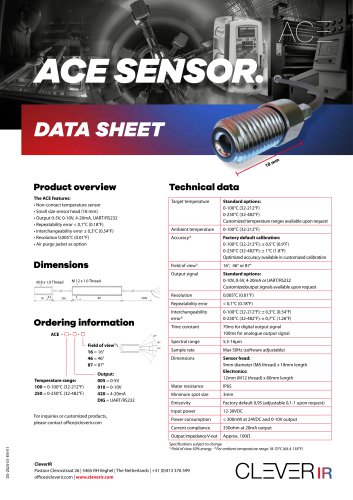 ACE SENSOR.
1 Page
 SMART IRT/C.07
1 Page
 SMART IRT/C.03
1 Page
 IRT/C.100A BASE MODEL
1 Page
 IRT/C.20A BASE MODEL
1 Page
 IRt/c.10A Base Model
1 Page
 SmartIRt/c
2 Pages
 Brochure Tri Fold
2 Pages
 Micro IRt/c
1 Page


- Waterproof temperature sensor
- Stainless steel temperature transducer
- Threaded temperature sensor
- Analog temperature sensor
- Precision temperature transducer
- IP65 temperature transducer
- Compact temperature probe
- High-temperature temperature sensor
- Air temperature probe
- Digital temperature sensor
- Flexible temperature sensor
- Temperature transducer with housing
- Infrared temperature sensor
- OEM temperature sensor
- Non-contact temperature sensor
- Intrinsically safe temperature sensor
- Miniature temperature sensor
- Custom temperature sensor