
- Catalogs
- Exceltec Canada Inc.
- Mineral Insulated (MI) Strip Heaters


Mineral Insulated (MI) Strip Heaters
Mineral Insulated (MI) Strip Heaters
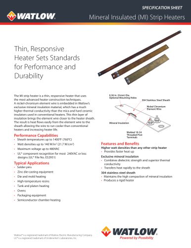
The Mineral Insulated (MI) strip heater is a thin, responsive heating device utilizing advanced construction techniques. It features a nickel-chromium element wire embedded in a proprietary mineral insulation, offering superior thermal conductivity compared to conventional mica and ceramic insulators. This design allows for efficient heat transfer and extended heater life.
Performance Capabilities
- Sheath temperatures up to 1400°F (760°C)
- Watt densities up to 140 W/in² (21.7 W/cm²)
- Maximum voltage up to 480VAC
- UL® component recognition for most designs at 240VAC or less
Features and Benefits
- Higher watt densities for faster heat-up
- Exclusive mineral insulation for rapid heat transfer and dielectric strength
- 304 stainless steel sheath for durability and rigidity
Typical Applications
- Solder pins
- Zinc die-casting equipment
- Die and mold heating
- High-temperature resins
- Tank and platen heating
- Ovens
- Packaging equipment
- Semiconductor chamber heating
Specifications
- Width: 1, 1½, and 2 inches (25, 38, 51 mm)
- Length: 8 to 30 inches (203 to 762 mm)
- Terminations: Post terminals with various configurations
Calculating Watt Density
Watt density is calculated by dividing the total wattage by the heated area. The heated area is determined by subtracting no-heat areas (around terminals, mounting holes) from the total contact surface.
Options and Accessories
- Thermocouple Pocket: For accurate temperature sensing
- Ceramic Terminal Covers: For insulating post terminals
Contact Information
For technical sales and support, contact Watlow's North American or International offices.
Catalog excerpts
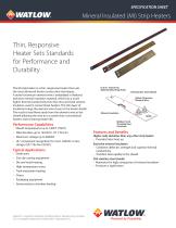
SPECIFICATION SHEET Thin, Responsive Heater Sets Standards for Performance and Durability The MI strip heater is a thin, responsive heater that uses the most advanced heater construction techniques. A nickel-chromium element wire is embedded in Watlow's exclusive mineral insulation material, which has a much higher thermal conductivity than the mica and hard ceramic insulators used in conventional heaters. This thin layer of insulation brings the element wire closer to the heater sheath. The result is heat flows easily from the element wire to the sheath allowing the wire to run cooler than conventional heaters and increasing heater life. • UL® component recognition for most 240VAC or less designs (UL® File No. E52951) • Solder pins • Zinc die-casting equipment • High-temperature resins • Tank and platen heating • Packaging equipment • Semiconductor chamber heating Higher watt densities than any other strip heater • Provides faster heat up Exclusive mineral insulation • Combines dielectric strength and superior thermal conductivity • Transfers heat rapidly to the sheath 304 stainless steel sheath • Maintains the high compaction of mineral insulation • Produces a rigid heater Watlow® is a registered trademark of Watlow Electric Manufacturing Company. UL® is a registered trademark of Underwriter's Laboratories, Inc.
Open the catalog to page 1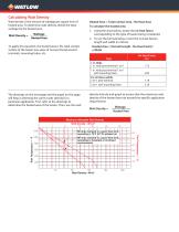
Calculating Watt Density Watt density is the amount of wattage per square inch of heated area. To determine watt density, divide the total wattage by the heated area. Watt Density = Wattage Heated Area To apply this equation, the heated area is the total contact surface of the heater less areas of no-heat found around terminals, mounting holes, etc. Heated Area = Total Contact Area - No-Heat Area To calculate the heated area: 1. Using the chart below, locate the no-heat factor corresponding to the type of heater being considered. 2. To use the formula below, insert the no-heat factors, length...
Open the catalog to page 2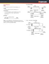
• 1, 11/2 and 2 in. (25, 38, 51 mm), tolerance ±1/32 Length Heated Length 7⁄8 in. 7⁄8 in. 1/8) (22.2± mm • 8 to(22.2 30 in. mm)(203 to 762 mm), tolerance ½ in. ½ in. 0.36 in. (9 mm) D, 2 Places Terminations (13 mm) (13 mm) • 1 in. (25 mm) wide—post terminals one-on-one 11/2 to 2 in. (38 to 51 mm)—post terminals 1½ in. 1½ in. two-on-one (38 mm) (38 mm) All Heated Length Heated Length Heated Length Heated Length Note: In most applications, mounting holes alone do not provide adequate clamping. A clamp bar should be used for each 4 in. (102 mm) of heater length. 10-24 Screw Thread 0.715 in. mm)...
Open the catalog to page 3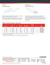
Thermocouple Pocket AccessoriesCeramic Terminal Covers A thermocouple pocket welded to the back surface accepts a 0.063 in. (1.6 mm) diameter thermocouple. This option provides accurate temperature sensing and easy thermocouple replacement. Thermocouple not included. Ceramic terminal covers offer a convenient and economic method to insulate post terminals. They are sized for standard length posts with 10-24 screw thread size, supplied as an accessory item and shipped separately. Specify Z4918 and quantity. Parallel Terminals Part Numbers-Type 3 and 4 Width in. (mm) ® Denotes units with mounting...
Open the catalog to page 4All Exceltec Canada Inc. catalogs and technical brochures
 SERIES 5900
3 Pages
 MICROCOIL
2 Pages
 SERIES 5750
3 Pages
 nanodac™ Recorder / Controller
12 Pages
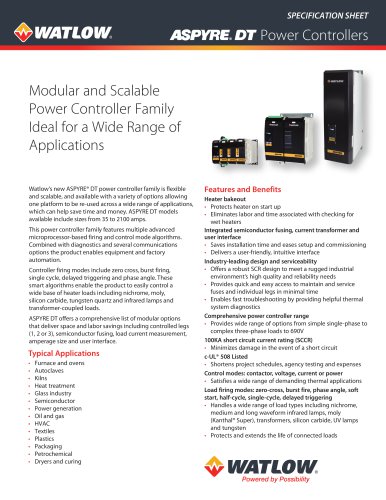 ASPYRE® DT power controller
8 Pages
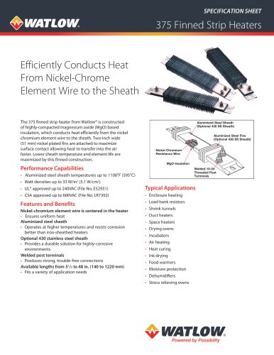 375 Finned Strip Heaters
4 Pages
 HYDROSAFE® Heat Exchanger
4 Pages
 Tubular Heaters
4 Pages
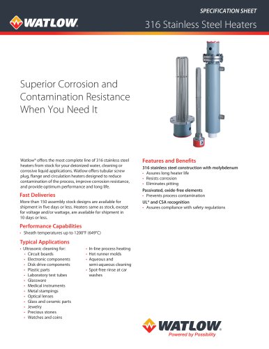 316 Stainless Steel Heaters
2 Pages
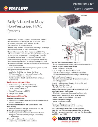 Duct Heaters
3 Pages
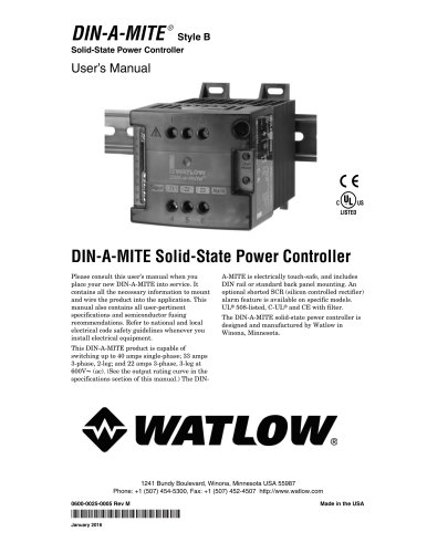 Solid-State Power Controller
13 Pages
- Temperature probe
- Data logger
- Resistance temperature sensor
- Pressure transmitter
- Analog pressure transmitter
- Temperature datalogger
- Membrane pressure transmitter
- Communication gateway
- Relative pressure transmitter
- Pt100 temperature transducer
- Temperature controller
- Digital pressure transmitter
- Fieldbus gateway
- Humidity and temperature probe
- Wireless datalogger
- Resistance heater
- Relative humidity and temperature sensor
- Wireless gateway
- RTD temperature sensor