
- Catalogs
- EWIKON Heißkanalsysteme GmbH
- HPS III-S nozzles Ø 9 mm


HPS III-S nozzles Ø 9 mm

HPS III-S nozzles Ø 9 mm
The document outlines the specifications and assembly instructions for HPS III-S Ø 9 mm hot runner nozzles, which are externally heated and utilize tip sealing technology. It covers standard and front installation methods and various nozzle versions tailored for different materials and applications.
The nozzles come in multiple versions, each designed for specific materials and applications. Key dimensions include the distance from the lower edge of the nozzle body to the article surface (Dim. X) and gate diameters (ØD). The material grade option -W4 is recommended for reinforced resins and materials with high filler content.
The document describes several gating geometries, including nozzle inserts with tips and open tips. Options include standard and extended screw-on gate bushes, with or without ball geometry, suitable for rapidly freezing or reinforced materials.
Instructions are provided for installing the nozzle body and shaft for both standard and front installations. Correct installation geometry in the gate area is emphasized, with specific recommendations for different material types.
It is crucial that the gate diameter of open tip inserts is at least 0.5 mm smaller than the diameter of the insert. For different gate diameters, consultation with EWIKON is advised.
1. Standard nozzle geometry has a diameter (ØD) ranging from 1.5 mm to 3.5 mm, applicable to reinforced materials as well.
2. For specific nozzle types (95308-V01 and 95309-V01), the standard geometry ØD is 2.5 mm, with a maximum of 4.0 mm.
1. Pre-machine the contour and harden it to 52 HCR before finalizing the gate geometry and nozzle tip fitting.
2. For open tip nozzles, ensure the gate diameter is at least 0.5 mm smaller than the nozzle tip diameter. Consult EWIKON for different gate diameters.
1. Installation can be performed with either a gate bush or a screw-on gate bush.
2. For dimensions X greater than 150 mm, use a specific locating bush (83002).
1. Standard material (-V01) and wear-resistant material (-V02) options are available for different nozzle types.
1. When ordering, specify the dimension X, type, material grade option, and ØD.
Catalog excerpts

14 - 19 Einbauhinweise Assembly notes 20 - 22 Vorkammerbuchsen Gate bushes Alle Ma&e in diesem Katalog beziehen sich auf EWIKON Hei&kanalkomponenten im aufgeheizten Betriebszustand All dimensions in this catalogue refer to EWIKON hotrunner components in heated operating condition
Open the catalog to page 1
EWIKON HPS III-S 0 9 mm Overview Auftenbeheizt, mit Spitzendichtung Standardmontage 95308-V01 . . . Frontmontage 95309-V01 . . . 0 „ D) 3 Externally heated, with tip sealing technology Standard installation 95308-V01 . . . Front installation 95309-V01 . . . 1 For use with pressure pad 17536 for manifold
Open the catalog to page 2
Einzeldüsen Single nozzles Heißkanaldüsen · Nozzles Verteilersysteme Manifold systems Zentrierringe Angießbuchsen Locating rings Sprue bushings Außenbeheizt, mit Spitzendichtung Standardmontage 95308-V01 . . . Frontmontage 95309-V01 . . . Externally heated, with tip sealing technology Standard installation 95308-V01 . . . Front installation 95309-V01 . . . Gating geometries Nozzle insert with tip Kontur direkt im Einsatz (2) Kontur direkt im Einsatz mit Kugelkalotte (3) für schnellerstarrende oder verstärkte Materialien Vorkammerbuchse Standard Vorkammerbuchse mit Kugelkalotte für schnellerstarrende...
Open the catalog to page 4
E E fc £ -£■ u) <£ >, </) £ -O =i £ £ ^
Open the catalog to page 5
HPS III-S 0 9 mm Nozzle version -A (-W4) -A Contour directly in the insert or with gate bush -W4 For reinforced materials or materials with a high percentage of fillers Standard installation 95308-V01 . . . Nozzle insert with tip Dim. X: 050 / 070 / 090 / 110 / 130 / 150 180 / 200 mm UJ (0 HPS III-S 0 9 mm Heiftkanalduse Version -A (-W4) -A Kontur direkt im Einsatz oder mit Vorkammerbuchse £= </) 0 0) -W4 zur Verwendung bei verstarkten Materiaiien oder Materiaiien mit hohem FuNstoffanteM (D C o Q-Standardmontage 95308-V01 . . . Dusenspitze mit Spitze MaB X: 050/070/090/ 110/ 130/ 150 180 / 200...
Open the catalog to page 6
Einzeldüsen Single nozzles Heißkanaldüsen · Nozzles -W4 zur Verwendung bei verstärkten Materialien oder Materialien mit hohem Füllstoffanteil -W4 For reinforced materials or materials with a high percentage of fillers Front installation 95309-V01 . . . Nozzle insert with tip X = Lower edge of nozzle body to article surface 3 Kugelkalotte für schnellerstarrende oder verstärkte Materialien Contour directly in the insert or with gate bush 3 Ball geometry for rapidly freezing or reinforced materials Verteilersysteme Manifold systems Zentrierringe Angießbuchsen Locating rings Sprue bushings -A Kontur...
Open the catalog to page 8
Einzeldüsen Single nozzles Heißkanaldüsen · Nozzles Nozzle version -B1/B2 · -C1/-C2 -B1 Standard screw-on gate bush -B2 Schraubvorkammer mit Kugelkalotte für schnellerstarrende oder verstärkte Materialien -B2 Screw-on gate bush with ball geometry for rapidly freezing or reinforced materials Standard installation 95308-V01 . . . Front installation 95309-V01 . . . Nozzle insert with tip -C1 verlängerte Schraubvorkammer Standard -C2 verlängerte Schraubvorkammer mit Kugelkalotte für schnellerstarrende oder verstärkte Materialien -C2 Extended screw-on gate bush with ball geometry for rapidly freezing...
Open the catalog to page 10
Einzeldüsen Single nozzles Heißkanaldüsen · Nozzles Zentrierringe Angießbuchsen Locating rings Sprue bushings Kontur direkt im Einsatz oder mit Vorkammerbuchse Standard Contour directly in the insert or with standard gate bush Standard installation 95308-V01 . . . Front installation 95309-V01 . . . Schraubvorkammer Standard Standard screw-on gate bush Verteilersysteme Manifold systems Standard installation 95308-V01 . . . Front installation 95309-V01 . . . verlängerte Schraubvorkammer Standard Extended standard screw-on gate bush Standard installation 95308-V01 . . . Front installation 95309-V01...
Open the catalog to page 12
Einzeldüsen Single nozzles Heißkanaldüsen · Nozzles Zubehör Accessories Allgemeine Einbauhinweise General Assembly notes Verteilersysteme Manifold systems Zentrierringe Angießbuchsen Locating rings Spr
Open the catalog to page 13
Einzeldüsen Single nozzles Heißkanaldüsen · Nozzles Assembly notes 1 Fixierung der Düse für den Spitzenwechsel im Werkzeug 1 Locating pin when tip inserts need to be exchanged in mould 2 Installation with gate bush 3 Installation with screw-on gate bush or directly in the insert Verteilersysteme Manifold systems Installation of nozzle body and shaft Standard installation 95308-V01 . . . 3 Einbau mit Schraubvorkammer oder direkt im Einsatz Zentrierringe Angießbuchsen Locating rings Sprue bushings Einbau Düsenkörper und -schaft Standardmontage 95308-V01 . . . Zubehör Accessories Allgemeine Einbauhinweise...
Open the catalog to page 14
Einbau Dusenkorper und -schaft Frontmontage 95309-V01 . . . 1 Einbau mit Schraubvorkammer oder direkt im Einsatz 2 Einbau mit Vorkammerbuchse 1 Installation with screw-on gate bush or directly in the insert 2 Installation with gate bush
Open the catalog to page 15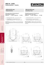
Installation geometry in the gate area contour directly in the insert 95308-V01 . . . -A (-W4) ■ 95309-V01 . . . -A (-W4) 1 Standard geometry 0D = 1.5 mm, max 3.5 mm 2 With ball geometry for rapidly freezing or reinforced materials, 0D = 1.5 mm, max 3.5 mm Einbaugeometrie im Anspritzbereich Kontur direkt im Einsatz 95308-V01 . . . -A (-W4) ■ 95309-V01 . . . -A (-W4) 0 D) (D <2 □> .£ O) -ft g -£= 1 Standardgeometrie: 0D = 1,5 mm, max. 3,5 mm -t—1 ~~~ 0 3 2 mit Kugelkalotte fur schnellerstarrende oder verstarkte Materialien, 0D = 1,5 mm, max. 3,5 mm Empfehlung: Kontur vorfertigen und auf...
Open the catalog to page 16
Einzeldüsen Single nozzles Heißkanaldüsen · Nozzles Assembly notes Installation geometry in the gate area contour directly in the insert 95308-V01 . . . -D · 95309-V01 . . . -D Empfehlung: Kontur vorfertigen und auf 52 HCR härten. Danach Anspritzgeometrie und Passung der Düsenspitze fertigstellen. Recommendation: Machine contour and harden to 52 HCR. Afterwards machine gate geometry and fit for nozzle tip. Bei offenen Düsen muss der Anspritz-Ø der Vorkammergeometrie immer mindestens 0,5 mm kleiner sein als der Ø der Düsenspitze. Sollte ein anderer AnspritzØ gewünscht werden, bitte Rücksprache...
Open the catalog to page 17All EWIKON Heißkanalsysteme GmbH catalogs and technical brochures
 L2X Drop-In System 2024
15 Pages



Archived catalogs
 Hotline October 2015 online
8 Pages
 HPS III-SXE
8 Pages
 HPS-C 2011
20 Pages
 HPS III-MV multi-tip nozzles
12 Pages
 Slim high performance nozzle
2 Pages
 Hotline May 2015 online
8 Pages
 HPS III-S nozzles Ø 4.5 mm
20 Pages
 HPS III-S open nozzle Ø 18 mm
16 Pages
 Product guide
26 Pages
 HPS-C hotrunner controllers
2 Pages
 Mechanical gap filter
6 Pages
 New "Hotline" online
8 Pages
 HPS III-FleX
20 Pages
 HPS III-S nozzles Ø 6 mm
22 Pages
 L2X
L2X8 Pages
 HPS III-S nozzles Ø 12 mm
22 Pages
 HPS III-S nozzles Ø 3 mm
20 Pages
 HPS III-MH
74 Pages


- Digital temperature control
- Liquid nozzle
- Stainless steel nozzle
- Metal nozzle
- Multi-jet nozzle
- Screw-in single nozzle
- Temperature control unit
- Digital temperature control unit
- Compact nozzle
- Injection nozzle
- Process temperature control unit
- Nozzle for pharmaceutical applications
- Air-operated nozzle
- Remote control unit
- Automation temperature control unit
- Compact control unit
- Temperature control unit with touchscreen
- Hydraulic nozzle
- Hot runner system