- Company
- Products
- Catalogs
- News & Trends
- Exhibitions
CASM 100 - Operating manual
1 /28Pages

CASM 100 - Operating manual
1 /28Pages
Catalog excerpts
7.5.7 Parallel gearbox and motor adapter installation ... 19 Read this manual before installing, operating or maintaining this actuator. Failure to follow safety precautions and instructions could cause actuator failure and result in serious injury, death or property damage.
Open the catalog to page 3
1.1 Information about this manual This manual provides important information on how to work with the actuator (also called device or drive) safely and efficiently. The manual is part of the device, must always be kept in the device’s direct proximity and should be available for person- Indicates a dangerous situation, which will lead to death or serious personal injury, if the precautionary measures are ignored. WARNING Indicates a dangerous situation, which can lead to minor or moderate injury or property damage, if the precautionary measures are ignored. nel to read at any time . All personnel...
Open the catalog to page 4
All information and notes in this manual were compiled un- The CASM-100 linear actuator is not meant to be repaired by present status of technology and our years of knowledge void without notice if any screws on the linear actuator have der due consideration of valid standards and regulations, the and experience. The manufacturer will not be liable for damage resulting from: • disregarding this manual • unintended use • employment of untrained personnel • unauthorized conversions customer personnel . All warranty and service claims become been loosened or removed (⮑ 9 Malfunctions, page 24)....
Open the catalog to page 5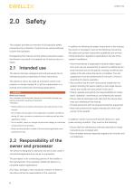
This chapter provides an overview of all important safety precautions for protection of personnel as well as safe and trouble-free operation. Disregarding this manual and the safety precautions specified therein may result in increased risk of serious injury or death. 2.1 Intended use The device has been designed and built exclusively for its intended purpose as described in these instructions. The device is only to be used as a dynamic centric com- pression or tensile-loaded lift. It will be implemented in industrial and construction technology applications. WARNING Risk from misuse! Any utilization...
Open the catalog to page 6
2.3 Personnel requirements WARNING Improper installation, operation and maintenance can result in serious injury, death or property damage. Use only qualified, trained personnel (as described below) who have read, understand and follow these instructions. 2.3.1 Qualifications The following qualifications are specified for different areas a way that a disruption of the power supply or the reactivation of the power supply after a power disruption cannot cause a hazardous situation for persons and objects. The emergency shut-off system must always be easily accessible. The processor must decide...
Open the catalog to page 7
The technical data (dimensions, weight, output, connection values, etc.) can be found in the drawings and data sheets at the end of this manual (⮑ 11 Appendix, page 27). 3.1 Operating conditions Environment Information Temperature range Relative atmospheric humidity, maximum (no build up of condensation) The gearbox product label can only be found on the prod- uct, if the gearbox (e.g. inline gearbox, spur gearbox) was ordered separately. If the actuator was ordered with a gearbox, the main product label contains all information (⮑ The outside temperature of the actuator should not exceed 60°C....
Open the catalog to page 8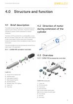
4.1 Brief description The CASM-100 (see image below) is a mechanical drive designed to work in factory automation. The drive is used exclusively for dynamic center compression or traction movement. 4.2 Direction of motor during extension of the cylinder The linear unit (7) is powered thru a coupling (5) by a motor (6). The motor (6), in direct drive, set in motion either a ball or a roller screw system. Via the screw mount, the system transforms the rotation of the motor (6) into a linear motion of the actuator. The push tube (8) and the other accessories transmit the ac- tuator power in the...
Open the catalog to page 9
4.4 Sensor mounting • Sensor can be inserted in two slots s on the CASM-100 electro cylinder (see image below). • Install the sensors: the sensors can be inserted into the slots from above. The cable ends should lead into the drive direction. Push the sensors to their approximate positions in the slots of the cylinder body. Tighten the fixing screws on the limit switches slightly and lead the cable along the profile slots.
Open the catalog to page 10
5.0 Delivery, packaging and storage 5.1 Safety information for 5.3 Returning actuator to transport the manufacturer NOTICE Damage due to improper transporting Significant material damage can occur in conjunction with improper transport. Therefore: • Proceed carefully during the unloading and delivery of the packaged items to its final destination and comply with the information shown on the packaging. • Only remove the actuator from its packaging right before installation. • Note storage requirements if actuator needs to be returned to the manufacturer (see 5.5 Storage, page 17). Proceed as follows...
Open the catalog to page 11
EWELLIX 5.5 Storage Pack the actuator in its original packaging for storage. • Do not store outside. • Storage should be dry and dust-free. • Keep away from any aggressive media. • Protect from UV radiation. • Avoid mechanical vibrations. • Storage temperature: -40 to 50 °C. • Relative atmospheric humidity: max. 95% (no build up of condensation). • To store longer than three months, check the general condition of all parts of the packaging on a monthly basis. If necessary, refresh or renew the conservation. It is possible that there are notices on the packaging concerning storage which go beyond...
Open the catalog to page 12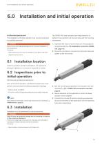
6.0 Installation and initial operation Authorized personnel The installation and initial operation may only be conducted by qualified personnel. WARNING Risk of injury and material damage due to incorrect installation of the accessories Therefore: • Optional devices may only be installed in accordance with their respective instructions. The CASM-100 Linear actuator (see image below) is at- tached to two elements via the push tube and the mounting accessories. 1. Assemble the motor onto the linear unit if the product is not premounted (⮑ 7.5 Installation instruction CASM100, page 16). 2. Screw...
Open the catalog to page 13All EWELLIX catalogs and technical brochures
 LIFTKIT-TM
8 Pages
 LIFTKIT-0S
8 Pages
 LIFTKIT-OM
8 Pages
 SLIDEKIT 2.0
12 Pages
 Telescopic pillar TLG
6 Pages
 Servo actuator SEMC
12 Pages
 Electric cylinders CEMC
12 Pages
 Electric cylinders CASM-25
8 Pages
 Linear actuator CAMT
10 Pages
 Telescopic pillar FRE
4 Pages
 Telescopic pillar TXG
6 Pages
 Telescopic pillar TLT
6 Pages
 Telescopic pillar TLC
6 Pages
 THG
THG6 Pages
 Telescopic pillar TFG
6 Pages
 CPMB
CPMB10 Pages
 Telescopic pillar CPMT
8 Pages
 CPMA
CPMA10 Pages
 Linear actuator Ecomag
6 Pages
 Linear actuator CAJA35C
6 Pages
 Linear actuator Runner
6 Pages
 Linear actuator CAHB series
56 Pages
 Electric cylinders LEMC
48 Pages
 Electric cylinders CASM-32/40/63
68 Pages
 Operating switches
28 Pages
 Control units
26 Pages
 Linear actuator Matrix series
16 Pages
 Profile rail guides catalogue - LLT
116 Pages
 High performance actuator catalogue
304 Pages
 High power density solution
2 Pages
 Ewellix precision ball screws
16 Pages
 Linear technology for joining
20 Pages
 Linear modules and systems
50 Pages
 Precision rail guides catalogue
116 Pages
 Solutions for imaging equipment
16 Pages
 Ball Screws
4 Pages
 Roller screw catalogue
134 Pages
 Aerodynamic booster actuator
8 Pages
 Solutions for mobile machinery
20 Pages
 Actuator range catalogue
310 Pages
 Roller screws catalogue
134 Pages
 SVC 8x1R 62/62 G3
3 Pages
 Linear actuator Magdrive
6 Pages
 LLU catalogue
74 Pages
 CASM 100 - data sheet
38 Pages
 Fluid power replacement
28 Pages
 Servo pillar CPSM
10 Pages
 ewellix brochure
5 Pages
 Car transfer unit solutions
12 Pages


