


Mentor Software

Mentor Software
The MENTOR 12 is a sophisticated three-phase relay test set designed for testing electromechanical and digital protections. It features a manual control interface accessible via a touch screen and rotary selector, with optional external peripherals.
- Full Direct Control: Allows manual testing without a PC, featuring power source controls, measurement displays, and event logging.
- Configuration Control: Modular design supports easy addition of channels and configuration of power outputs, binary inputs, and outputs.
- Assisted Control: Provides on-screen regulation of complex magnitudes like impedance and power sequences.
- Vector View: Offers control over phasors with module and angle lock functions.
- Test Functions: Includes built-in test functions for protection relays, fault configurations, and ramp testing.
- State Sequencer: A programmable tool for testing protection schemes and logical sequences.
- Fault Playback (COMTRADE): Enables playback and analysis of transient fault data.
- Results Manager: Facilitates test result storage and reporting.
- Remote Control: Supports local and remote operation via serial or Ethernet connections.
- Battery Simulator: Provides auxiliary DC supply for relay powering.
- Harmonics Control: Allows selection of harmonic content and angle in each channel.
- Smart Test Tools: Optional tools for importing RIO files and executing tests without a PC.
- IEC-61850 – GOOSE: Testing according to IEC 61850 standards with configuration tools.
- Internet Upgrading & Maintenance: Supports online updates and diagnostics.
- Automatic Import of Relay Settings: Automates the import and update of relay settings using pattern recognition.
- Data Settings Panel: Offers a tree classification system for data management.
- General Report Tool: Combines reports from different modules into a single document.
- Characteristics Editor & Templates: Provides a graphic editor for protective areas and curves.
- Formulas: User-programmable test engine in Visual Basic.Net.
- Fault Calculation & Sequential Test Execution: Ensures accurate fault calculation and test assessment.
The MENTOR 12 is a versatile and advanced tool for relay testing, offering a wide range of functionalities and modular configurations to meet diverse testing needs. Its intuitive interface and comprehensive features make it suitable for both commissioning and maintenance tasks.
- Test Functions: The document describes several test functions including Fault, Ramp, Pulse Ramp, Binary Search, State Sequencer, and Fault Playback. Each function is designed to test different aspects of relay performance under various conditions.
- Fault Function: Allows setting and executing prefault, fault, and postfault values, displaying results in graphical and numeric modes.
- Ramp Function: Enables programming and executing single and double ramps to determine trip levels of protection relays.
- Pulse Ramp Function: Similar to Ramp but uses preset conditions between pulses, useful for testing overcurrent elements.
- Binary Search Function: Adapts to different values for effective trip value search, unlike fixed increase ramps.
- State Sequencer Function: Tests protection schemes by programming sequences of outputs in logical states.
- Fault Playback: Plays back COMTRADE fault files to analyze protection behavior against recorded or simulated faults.
- Results Manager: Saves test results and configurations for future use, allowing automation of tests for specific relays.
- Internet Upgrading and Maintenance: Provides software updates and hardware options via the internet, ensuring the device remains up-to-date.
- Meter & Measuring: Configures settings for analog and binary measurements, testing transducers and counters.
- Binary I/O Monitor: Monitors binary input and output states, facilitating relay reaction testing.
- Battery Simulator: Built-in simulator for supplying relays requiring auxiliary power.
- Timer Settings: Allows quick adjustment of timer start and stop conditions for testing needs.
- Logger: Automatically records events for performance analysis.
- Harmonics Control: Regulates harmonic content in voltage and current channels for testing purposes.
- Cape Test Files Converter: Converts Cape SS1 files for use with MENTOR 12, facilitating quick test execution.
- IEC-61850 GOOSE Module: Ensures compatibility with IEC-61850 standards for GOOSE messages.
The document provides a detailed overview of the functionalities and optional modules available for the MENTOR 12 unit, a device used for testing and synchronizing electrical systems. It highlights the integration of various technologies and software tools to enhance the unit's capabilities.
The MENTOR 12 unit can be configured to work with the IEC 61850 protocol through an RJ-45 connector. This allows the unit to use GOOSE messages as logic inputs and outputs, eliminating the need for physical wiring to relay inputs and outputs. The configuration software is embedded within the MENTOR 12, negating the need for an external computer.
For tests requiring synchronization of multiple MENTOR 12 units, high precision reference clocks such as GPS and IRIG/B can be used. These options allow for microsecond precision in triggering sequences or reproducing fault playback. The GPS signal is globally accessible, while IRIG/B requires a local setup.
STT is an optional software that enables automatic stand-alone testing of distance elements. It allows for the execution of ROOTS-originated test files without an external computer. Test results are stored on a USB drive and can be retrieved and associated with corresponding relays for reporting.
Vector View: Provides control over phasors with module and angle lock functions, allowing users to adjust amplitude and phase angle by dragging vectors on the screen.
Assisted Control: Offers direct regulation of complex magnitudes and calculates electrical situations based on user inputs. It includes features for fault impedance, voltage, current, and power disturbance settings.
Summary Window: Displays a simplified vector representation or a summary of impedance and power values, aiding in regulation during direct control.
ROOTS is a software solution for testing multifunctional IEDs, providing fault calculation, test execution, and reporting. It supports database management, test routine customization, and offers free lifetime updates. ROOTS can be used with MENTOR 12 for executing test procedures without an external computer.
The ROOTS software includes a Data Settings Panel for managing relay settings and templates. It supports automatic import of relay settings from text files using pattern recognition and templates, ensuring accurate testing with correct settings provided by the protection department.
The ROOTS system allows for comprehensive management of databases and devices, enabling users to create multiple test databases. Each database is organized by devices, which include specific device definitions, relay settings, protection modules, characteristics, test routines, results, and reports. Users can assign functions, custom variables, default variables, and test modules to each device. Devices can be organized and grouped for easier management and test plan creation. The system supports XML import/export for device data, facilitating the use of test templates across different databases.
Report Configuration
Upon test completion, reports are automatically generated in PDF, HTML, or Word RTF formats. Users can configure which sections to include in the report and select images or logos for display. A General Report tool allows for combining different test reports into a single document.
Overcurrent Module
This module tests protective devices implementing various protection functions (e.g., 50, 51, 67). It includes sections for technical data, element lists, characteristics templates, and test lists. Users can configure test settings, points, and results assessment. The module supports various test types, such as Click Sequence, Pick up/drop out, Reclose, and more, with automatic report generation.
Distance Module
The Distance test module is used for testing protection functions related to IEEE number 21. It includes sections for technical data, distance zones, graphical characteristic editor, and test lists. Users can configure test models, settings, points, and results assessment. The module supports various test types, including Click Sequence, Search, Verification Test, and more, with automatic report generation.
- Point Sequentially: Determines if an operation has occurred and evaluates the operation time against theoretical time in the relay's characteristic.
- Search Test: Locates the boundaries of the relay's characteristic by injecting a series of consecutive faults.
- Technical Data: Configures up to 6 feeders connected to the busbar, including CT data settings and directional blocking techniques.
- Operating Characteristic: Allows editing of relay characteristics using predefined types or custom building.
- Test List: Includes verification, click sequence, search, and breaker fail tests.
- Three-phase Voltage Module: Checks the operation of three-phase voltage relays.
- Single-Phase Voltage Module: Checks the operation of voltage relays with one measuring voltage.
- Technical Data: Sets up general parameters like voltage input connection and tolerances.
- Elements: Configures relay characteristics and operating times, including over and undervoltage adjustments.
- Technical Data: Configures general parameters like voltage, time, frequency, and dF/dT tolerances.
- Elements: Adjusts and configures elements and operating times for frequency-dependent functions.
- Test List: Includes tests like Click Sequence Frequency Test and Pick Up/Drop Out Frequency test.
Catalog excerpts
MENTOR SOFTWARE OVERVIEW
Open the catalog to page 1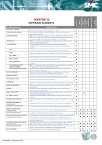
Easy control of all Power source combinations, Binary I/O configurations, visual connection guide NEW! On screen direct regulation of complex magnitudes: Impedance, Fault, Power (P,Q,S, Power Factor), Sequences (Symmetrical components), Vline and Homopolar Voltage, Open Delta. Also available in State Sequencer. NEW! Full control at your fingertips of individual or grouped phasors, with module and angle lock functions. The most complete Built‐in Test functions, with on‐screen graphic configuration, to carry out typical test for protection relays and protection schemes. VECTOR VIEW ...
Open the catalog to page 2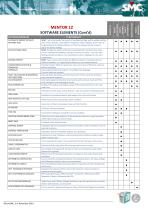
ROOTS FREQUENCY ROOTS OVERCURRENT ROOTS DISTANCE ROOTS DIFFERENTIAL NEW! Tool to automate the import of variables/settings and/or update existing ones, from a text file, using Pattern recognition and Templates. Source file can be generated by the Relay software, or from the Engineering file issued to adjust the device settings NEW! Besides the edition of the data associated with the device (Formulas, Custom and Default Variables) included in previous versions, this new Data Settings window includes a tree classification system, displayed to the user´s convenience NEW! Tool to select and combine the different reports of executed tests in ...
Open the catalog to page 3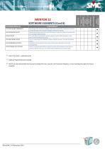
SOFTWARE/MODULES VOLTAGE INHIBIT FREQUENCY CLICK SEQUENCE DF/DT PICK UP DF/DT VOLTAGE INHIBIT DF/DT CLICK SEQUENCE VOLT/HZ PICK UP/DROP OUT VOLT/HZ FUNCTIONALITY Searching of the minimum voltage value that prevents the frequency elements to operate when the measured voltage is below the setting. Generation of test points list, each one being a frequency ramp, to evaluate the trip setting of df/dt element This test allows searching for pickup values of active df/dt elements in the device with the desired accuracy. Test for searching the inhibition voltage of df/dt elements, through frequency ...
Open the catalog to page 4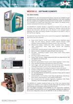
MENTOR 12 ‐ SOFTWARE ELEMENTS FULL DIRECT CONTROL The MENTOR 12 is the most advanced three‐phase relay test set available for type and field testing of electromechanical and digital protections of any kind, providing the most complete and straightforward Manual Control of the market. The MENTOR 12 is controlled via a touch screen panel and a rotary selector. An external mouse, monitor and keyboard can also be used if desired. The MENTOR 12’s intuitive interface is organized to complete the job safely and accurately in the shortest possible time. ...
Open the catalog to page 5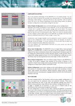
CONFIGURATION CONTROL One of the greatest advantages of the MENTOR 12 is its modular design. You can start with a basic 6‐channel unit and add more channels later on. The plug and play technology makes adding or replacing channels an easy operation, with no need to return the unit to the factory. Depending on the device being tested, the default hardware configuration can be quickly changed at any time: Power Outputs Configuration: Easy control of all Power sources configurations. Regardless the number of amplifiers in your MENTOR 12, you can also combine them ...
Open the catalog to page 6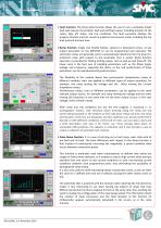
Fault function: this three‐state function allows the user to set a complete simple fault and execute the prefault, fault and postfault values, including duration of the states, logic I/O states, and trip conditions. The fault execution displays the progress timeline and test results in graphical and numeric mode, including the trip time and end function time. Ramp function: Single and Double Ramps, upward or downward ramps, of any output parameter on the MENTOR 12 can be programmed and executed. The automatic ramps are generally used to ...
Open the catalog to page 7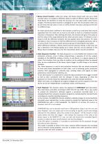
Binary Search function, unlike the ramps, the Binary Search does not use a fixed increase value, as it adapts to different values to make an effective search. Ramp and Pulse Ramp are excellent to verify the accuracy of a trip value within some known margins. The Binary Search function is designed to cover the circumstance when you do not know the trip value or even, to verify a known trip value carrying out the test in a different way. An initial search point is defined in this function as well as an end point that may be separated from the initial one as much as we want as well as a maximum function ...
Open the catalog to page 8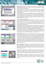
Results Manager: The Results Manager allows saving both the test results and configuration of Advanced test functions, so that they can be repeated as desired. Results are saved in a USB pendrive. The system can save as many tests as needed in Report files, being a way to automate tests for specific relays. The reports can be displayed on the PC, exported and/or printed, using the Report Viewer for Windows, which is included as standard in every MENTOR. After any advanced function test, we can add the results to any existing report, with a new name for this test and a description. The test is recorded with date and time ...
Open the catalog to page 9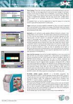
Timer Settings: Timer start and stop conditions can be quickly adjusted to the test needs. The timer can be programmed to start by the status changes in the Power Outputs, by the action of a Binary Input combination, or by the status change of any Binary Output. Timer stops by the trip action at the Binary Input logic, which setting is straightforward selected. After the stop of the timer, voltage and/or current outputs can be immediately switched off or delayed to simulate switch time. A countdown timer can also be programmed to ...
Open the catalog to page 10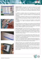
MENTOR‐GPS/IRIG‐B: Certain kind of test requires the setup of two or more MENTOR 12 units (or one MENTOR 12 and other test set) separated on different locations and synchronized with each other. In this case a very high precision reference clock is necessary, in order to obtain the required timing to trigger the state sequencer or the reproduction of Fault playback (COMTRADE files) on separate units. The MENTOR 12 equipment allows for this synchronism by the use of two alternatives of very precise time reference inputs: GPS and IRIG/B. Any of these two ...
Open the catalog to page 11All EUROSMC catalogs and technical brochures
 QUASAR
13 Pages
 RAPTOR System
7 Pages
 RAPTOR
7 Pages
 PTE range catalogue
8 Pages
 PTE-SER
2 Pages
 PTE-100-C Accessories
1 Page
 RAPTOR-PT Catalogue
1 Page
 PTE-FCG
2 Pages
 Eurofault
4 Pages
 Goosemeter One catalogue
4 Pages
 PTE-30-CH Catalogue
2 Pages
 PME-20-PH catalogue
2 Pages
 PME-500-TR
4 Pages
 Prime 600 Catalogue
4 Pages
 PTE-FCL
2 Pages
 PTE range
8 Pages
 PTE-100-C
8 Pages
 MENTOR 12
16 Pages
 TriRaptor
3 Pages
 RAPTOR HV
2 Pages
 SMC Short Form Catalogue_english
40 Pages
 PTE-100-C_PLUS_PRO
8 Pages

- Power supply unit
- DC power supply
- Electrical cable
- AC/DC power supply
- Temperature probe
- Copper cable
- Copper electrical cable
- Power cable
- Insulated cable
- Insulated electrical cable
- Portable tester
- Flexible cable
- Portable analyzer
- Flexible electrical cable
- Digital tester
- Real-time analyzer
- Industrial cable
- Industrial tester
- Tabletop power supply
- Switch electrical cable