
- Catalogs
- EUCHNER GmbH + Co. KG
- Safety Switches with Plastic Housing


Safety Switches with Plastic Housing

Safety Switches with Plastic Housing
- BiState Version: Maintains the guard locking pin in its position during power failure, preventing accidental entrapment.
- Twin Version: Allows simultaneous monitoring and locking of two movable guards.
- Installation: Safety switches can be mounted according to DIN EN 50047 standards or with 40 mm spacing. The approach direction is adjustable in 90° steps both horizontally and vertically.
- Ordering: Actuators must be ordered separately, with specific order numbers provided for each configuration.
- Mounting and connection specifications adhere to DIN EN 50047 standards.
- Ensure correct actuator ordering as per the specified pages for compatibility.
- Consider optional plug connectors for enhanced connectivity.
- Ordering Table: Lists series, actuator type, connection, housing, switching element, and order numbers.
- Selection Table: Provides options for different safety switch types, including NP, GP, and SGP, with details on connection types and switching elements.
- Ensure the correct torque (M=0.6Nm) is applied during installation.
- Actuators and plug connectors must be ordered separately, with references to specific pages for detailed information.
- Adjustable approach direction in 90° steps for both horizontal and vertical orientations.
- Increased horizontal overtravel for enhanced operational flexibility.
- Optional LED indicators for operational status monitoring.
- LED Indicators: Optional function displays for operational status.
- BI-State Function: Prevents unintentional locking during power failures.
General Specifications:
- Ambient Temperature: -20 to +80 °C
- Weight: Approx. 0.32 kg
- Approach Speed: Max. 20 m/min
- Actuating and Extraction Force: 25 N
- Retention Force: 10 N
- Insertion Depth: Actuator S standard, Lateral approach direction (h) 24.5 + 5 mm, Approach direction from above (v) 24.5 + 5 mm
Safety Switch SGA:
- Reliability: B10d 3 x 10⁶ operating cycles
- Connection: M20 x 1.5, Screw terminal
- Degree of Protection: IP 67
- Rated Insulation Voltage: Ui 250 V AC/DC
- Rated Impulse Withstand Voltage: Uimp 2.5 kV
- Conventional Thermal Current: Ith 4 A
- Short Circuit Protection: 4 A gG
- Utilization Category: AC-15 Ie 4 A Ue 230 V, DC-13 Ie 4 A Ue 24 V
- Switching Principle: Slow-action switching contact
- Contact Material: Silver alloy, gold flashed
Connection Types:
- Plug Connector SR11: 11-pin + PE, IP 65, Ui 50 V AC/DC
- Plug Connector M23 (RC18): 18-pin + PE, IP 65, Ui 110 V AC/DC
- Plug Connector SM8 (M12): 8-pin, IP 65, Ui 30 V AC/DC
- Plug Connector BHA12: 12-pin, IP 65, Ui 50 V AC/DC
Safety Switch TP with Guard Locking:
- Reliability: B10d 3 x 10⁶ operating cycles
- Locking Force: Max. 1,300 N
- Solenoid Operating Voltage: AC/DC 24 V, 110 V, 230 V
- Power Consumption: 8 W
Safety Switch STP with Guard Locking:
- Reliability: B10d STP 5 x 10⁶, STP-BI 2 x 10⁶ operating cycles
- Locking Force: Max. 2,500 N
- Solenoid Operating Voltage: AC/DC 24 V, 110 V, 230 V
- Power Consumption: 8 W
Switching Functions:
- Various configurations for door monitoring and unlock request contacts, with different combinations of normally closed (NC) and normally open (NO) contacts.
Note: All technical data are subject to modifications and no responsibility is accepted for the accuracy of this information.
1. Materials and Construction: The housing is made of reinforced thermoplastic, while the actuating head is die-cast aluminum with a stainless steel cam.
2. Mechanical Life: The switches have a mechanical life of 1 x 10⁶ operating cycles.
3. Temperature and Weight: Operates in ambient temperatures from -20 to +55 °C and weighs approximately 0.62 kg.
4. Forces: Actuating force is 35 N, extraction force (not locked) is 30 N, and retention force is 20 N.
5. Locking Forces: Maximum locking force is 2,500 N from both top and side approaches.
Switching Functions:
1. Switch Types: Various types including STP-TW, STA, STM, and TK with different configurations of normally closed (NC) and normally open (NO) contacts.
2. Switching Principle: Utilizes slow-action switching contacts with a minimum switching current of 1 mA at 24 V DC.
3. Contact Material: Made from silver alloy, gold flashed.
Guard Locking and Monitoring:
1. Solenoid Operating Voltage: 24 V AC/DC with a duty cycle of 100% and power consumption of 8 W.
2. Locking Force: Varies by model, with some models offering up to 5,000 N.
Connections and Protection:
1. Cable Entry: M20 x 1.5 screw terminal with a connection cross-section of 0.34 to 1.5 mm².
2. Degree of Protection: Rated IP 67 according to IEC 60529.
3. Rated Insulation Voltage: 250 V AC/DC with an impulse withstand voltage of 2.5 kV.
Reliability and Standards:
1. Reliability Values: B10d values range from 2 x 10⁶ to 11.5 x 10⁶ operating cycles depending on the model.
2. Compliance: Meets standards such as EN ISO 13849-1 and IEC 60947-5-1.
Accessories:
1. Connectors: Various types including M12, M23, and SR series with different pin configurations and protection ratings.
2. Built-in LED: Operates at 24 V DC with a current consumption of 45 mA.
Glossary:
1. Actuating Force: Defined as the minimum force required for a switching operation.
2. Approach Speed: The speed at which a switch can be mechanically actuated, dependent on the actuating element's shape and material.
- Specifications: The document lists numerous components with specific order numbers and page references. Each item is likely associated with detailed specifications on the referenced pages.
- Procedures and Standards: While not explicitly detailed in the provided text, the document likely includes installation or usage procedures and standards for each component, given the technical nature of the content.
- Contact Information: The document provides contact details for EUCHNER representatives in various countries, including Germany, Austria, Benelux, Brazil, Canada, and China. This section is crucial for customer support and inquiries.
- Order Numbers: Each component is associated with a unique order number, which is essential for identification and procurement.
- Page References: The page numbers next to each item suggest where detailed information can be found, which is critical for users needing specific data or instructions.
- Technical Modifications Disclaimer: The document includes a disclaimer about potential technical modifications and the accuracy of the information, indicating that users should verify details before proceeding with orders or installations.
Catalog excerpts

Safety Switches with Plastic Housing
Open the catalog to page 1
Internationally successful – the EUCHNER company EUCHNER GmbH + Co. KG is a world-leading company in the area of industrial safety technology. EUCHNER has been developing and producing high-quality switching systems for mechanical and systems engineering for more than 60 years. The medium-sized family-operated company based in Leinfelden, Germany, employs Headquarters in Leinfelden-Echterdingen around 750 people around the world. 18 subsidiaries and other sales partners in Germany and abroad work for our international success on the market. Quality and innovation – the EUCHNER products A look...
Open the catalog to page 2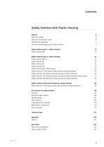
About this catalog 4 How can I find the right switch? 4 Function and technology used in safety switches 5 Safety switches type 1, plastic housing 13 Safety switches type 2, plastic housing 21 Safety switches NM..VZ 21 Safety switches SGA, metal housing 39 Safety switches TP with guard locking and guard locking monitoring 43 Safety switches STP with guard locking and guard locking monitoring 61 Safety switches STA with guard locking and guard locking monitoring, metal housing 75 Safety switches STM with guard locking and guard locking monitoring 83 Safety switches...
Open the catalog to page 3
General About this catalog The Safety Switches with Plastic Housing catalog gives you an overview of our safety switches and our rope pull switches. For numerous applications these switches are the right choice due to their economy and flexibility. You will find the technical data after the product overview. There is a reference to the page with the related technical data on the pages listing the products. At the front of the catalog you will find useful information on the topic of safety switches. We have prepared an overview of the standards and a glossary on this topic in the appendix. You...
Open the catalog to page 4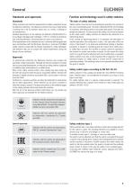
General EUCHNER Standards and approvals Standards Safety switches must meet the requirements for safety components as per the Machinery Directive. The Machinery Directive has been implemented in national law in the EU member states and, as a result, is binding for all manufacturers. Detailed requirements for the switches are defined in DIN EN 60947-5-1 (Low-voltage switchgear and controlgear - Part 5-1: Control circuit devices and switching elements. Electromechanical control circuit devices). If the requirements of this standard are met, conformity with the applicable laws and therefore with...
Open the catalog to page 5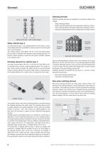
General Switching elements Different switching elements are available for the switches offered in the catalog: Single switching element Double switching element with two independent switching contacts Triple switching element with three independent switching contacts Quadruple switching element with four independent switching contacts Safety switch type 1 with rounded plunger Switching contact 2 Safety switches type 2 On safety switches type 2, the actuating element for the switch is coded. The actuating elements are available in various versions to suit the guard that is to be monitored. This...
Open the catalog to page 6
General Monitoring contacts On snap-action switching elements, the change from the completely closed state to the completely open state is made at a defined point. As a result the operating point is at a defined position, unlike on slow-action contact elements. Snap-action switching elements typically have a switching hysteresis. No snap-action switching elements are available for the safety switches in this catalog. Door monitoring contact and interlocking solenoid monitoring contact In addition to the safety contacts, monitoring contacts are also required, for example, to indicate the position...
Open the catalog to page 7
General This feature guarantees protection for anyone (e.g. maintenance or service personnel, or cleaning staff) who needs to enter potentially hazardous areas. The switches cannot signal a safe (closed) state with a lockout bar fitted. As a result unintentional starting of the machine is not possible. Guard locking Safety switches type 2 are available both with and without guard locking. Guard locking is a feature that prevents the unintentional opening of a door as long as there is a hazard. The door is locked by preventing the removal of the actuator from the safety switch. The series TP,...
Open the catalog to page 8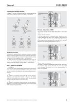
General Changing the switching direction Switch head Actuator Guard locking solenoid In addition, in the case of the NM.HB series, the actuating direction can be adjusted such that the actuator only switches in one direction. Rotate the actuating element Simultaneously press and rotate the washer Principle of operation of STM The sectional drawings show the safety switch STM in its three switch states: ᕡ Door open and not locked -90° Left switching Left / right switching (default setting) In the initial state (actuator removed/guard open) all positively driven contacts (SK and ÜK) are open. The...
Open the catalog to page 9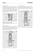
General ᕣ Door closed and locked After the actuator has been inserted, it is possible to activate the switch’s guard locking. If the guard locking solenoid is activated, the locking arm locks the plunger and actuates the switching element ÜK. The contacts 11-12 are closed on this switching element. The contacts 11-12 on the switching element SK continue to remain closed. In this position the positively driven contacts 11-12 on the two switching elements SK and ÜK are safely locked, the monitoring contact 23-24 is open. The actuator and the guard are locked. This means that the machine connected...
Open the catalog to page 10
General ᕣ Door closed and locked After the actuator has been inserted, it is possible to activate the switch’s guard locking. When the guard locking solenoid is activated, NO contact 33-34 is opened and signals the condition Locked. The NO contact 1314 signals the condition Door closed as before. The positively driven contacts 21-22 and 41-42 were closed when the guard locking solenoid was activated. The actuator and the guard are locked. This means that the machine connected to the safety circuit can be started. Door closed and locked The first guard locking pin is released by inserting the...
Open the catalog to page 11All EUCHNER GmbH + Co. KG catalogs and technical brochures
 Multifunctional Gate Box MGB
137 Pages
 Safety switch CTS
8 Pages
 EUCHNER Safety Services
24 Pages
 Logistics
5 Pages
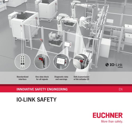 IO-Link Safety
4 Pages
 News
News6 Pages
 Safety Relays ESM
32 Pages
 Electronic-Key-System EKS2
6 Pages
 Safe key system CKS2
10 Pages
 Enabling Switches ZS
92 Pages
 About EUCHNER
34 Pages
 Safety Switches with Metal Housing
220 Pages
 Multiple Limit Switches
36 Pages
 Position Switches
56 Pages
 Safety Switches NQ/TQ
6 Pages
 Joystick Switches
28 Pages
 Electronic-Key-System
24 Pages


- Management software solution
- EUCHNER single-pole switch
- Windows software
- EUCHNER mechanical lock
- EUCHNER technology switch
- Interface software
- Multipole switch
- Visualization software solution
- Programming software
- EUCHNER door lock
- EUCHNER steel lock
- EUCHNER electromechanical switch
- Rotary electric switch
- EUCHNER limit switch
- EUCHNER zinc lock
- EUCHNER IP67 switch
- EUCHNER light curtain
- EUCHNER safety lock
- Touch switch