- Catalogs
- EUCHNER GmbH + Co. KG
- Safety Switches with AS-Interface
Safety Switches with AS-Interface
1 /52Pages

Safety Switches with AS-Interface
1 /52Pages
Catalog excerpts

Safety Switches with AS-Interface
Open the catalog to page 1
Internationally successful – the EUCHNER company EUCHNER GmbH + Co. KG is a world-leading company in the area of industrial safety technology. EUCHNER has been developing and producing high-quality switching systems for mechanical and systems engineering for more than 60 years. The medium-sized family-operated company based in Leinfelden, Germany, employs Headquarters in Leinfelden-Echterdingen around 800 people around the world. 18 subsidiaries and other sales partners in Germany and abroad work for our international success on the market. Quality and innovation – the EUCHNER products A look...
Open the catalog to page 2
Safety Switches with AS-Interface General 4 Safety Switches Type 1, Metal Housing Safety switch NZ with integrated actuator Safety Switches Type 2, Metal Housing Safety switch NZ.VZ Safety switch TZ with guard locking and guard lock monitoring Safety switch TX with guard locking and guard lock monitoring Safety switch STA with guard locking and guard lock monitoring Safety Switches Type 2, Plastic Housing Safety switch TP with guard locking Safety switch STP with guard locking and guard lock monitoring Safety switch STP-TW with guard locking and guard lock monitoring Magnetically Coded Safety...
Open the catalog to page 3
General AS-Interface Safety at Work in safety engineering Operation of AS-Interface Safety at Work AS-Interface (AS-i) is a low-level bus system that is used for the transfer of small data volumes. It is particularly suitable where digital signals must be collected in the field. The bus is very easy to set up and does not require any special programming tools. Simple address setting of the subscribers and an As-i master are all that is needed. Any required replacement of faulty components is very easy with ASInterface Safety at Work. A faulty bus subscriber is removed from the bus during operation...
Open the catalog to page 4
Safety Switches Type 1, Metal Housing Safety switch NZ with integrated actuator f Version A acc. to EN 50041 NZ.HS (steel roller ∅ 18) f Version C acc. to EN 50041 NZ.RS (steel roller ∅ 12 mm) Plug connector M12 4-pin Dimension drawing for NZ.RS Dimension drawing for NZ.HS Approach direction Version A acc. to EN 50041 NZ.HS/NZ.PS Horizontal Switch head and lever arm can be adjusted in 90° steps. Switching direction Right, left or both sides. Connector assignment Version C acc. to EN 50041 NZ.RS Horizontal Adjustable in 90° steps. AS-Interface inputs f D0, D1 Positively driven contact 1 f D2,...
Open the catalog to page 5
Safety Switches Type 2, Metal Housing Safety switch NZ.VZ f Housing according to EN 50041 Plug connector M12 4-pin Dimension drawing a Travel without operation: Actuator is in the guide slot, but function is not triggered. AS-Interface inputs f D0, D1 Positively driven contact 1 f D2, D3 Positively driven contact 2 Evaluation is performed via a safety monitor. Approach direction Horizontal Adjustable in 90° steps. b Switching operation completed: Actuator must be inserted to this point to ensure reliable switching. The actuator must be withdrawn at least to point a for switching off. AS-Interface...
Open the catalog to page 6
Safety Switches Type 2, Metal Housing Safety switch TZ with guard locking and guard lock monitoring Plug connector M12 4-pin Dimension drawings (actuator head on the left is a mirror image) Auxiliary release Guard locking types TZ1 Closed-circuit current principle, guard locking by spring force. Release by control of AS-i output 0. TZ2 Open-circuit current principle, guard locking by control of AS-i output 0. Release by spring force. b Switching operation completed: Actuator must be inserted to this point to ensure reliable switching. The actuator must be withdrawn at least to point a for switching...
Open the catalog to page 7
Safety Switches Type 2, Metal Housing Safety switch TZ with guard locking and guard lock monitoring Plug connector M12 4-pin Dimension drawings (actuator head on the left is a mirror image) Auxiliary release Guard locking type TZ1 Closed-circuit current principle, guard locking by spring force. Release by control of AS-i output 0. Fault Power a Travel without operation: Actuator is in the guide slot, but function is not triggered. b Switching operation completed: Actuator must be inserted to this point to ensure reliable switching. The actuator must be withdrawn at least to point a for switching...
Open the catalog to page 8
Safety Switches Type 2, Metal Housing Safety switch TX with guard locking and guard lock monitoring f Auxiliary release on the front Without escape release Plug connector M12, 4-pin Dimension drawing Insertion depth Approach direction Horizontal Adjustable in 90° steps. Insertion depth Auxiliary release This is used for releasing the guard locking with the aid of a tool. Auxiliary release LED indicator Locking screw Guard locking type TX1 Closed-circuit current principle, guard locking by spring force. Release by control of AS-i output 0. Control of the guard locking solenoid The guard locking...
Open the catalog to page 9
Safety Switches Type 2, Metal Housing Safety switch STA with guard locking and guard lock monitoring f Auxiliary release on the front Plug connector M12 4-pin Dimension drawing 30 h Insertion depth Guard locking type STA3 Closed-circuit current principle, guard locking by spring force. Release by control of AS-i output 0. STA4 Open-circuit current principle, guard locking by control of AS-i output 0. Release by spring force. Power Fault Control of the guard locking solenoid The guard locking solenoid is controlled by the control system via AS-Interface bus bit D0. In addition, the 24V connection...
Open the catalog to page 10
Safety Switches Type 2, Metal Housing Safety switches STA with guard locking and guard lock monitoring f Escape release on the rear f Auxiliary release on the front Plug connector M12 4-pin Dimension drawing 30 Insertion depth Insertion depth Escape release basic position v 35,5 Auxiliary release This is used for releasing the guard locking with the aid of a tool. Power Fault Plug connector not aligned AS-Interface inputs f D0, D1 Door monitoring contact SK f D2, D3 Solenoid monitoring contact ÜK Evaluation is performed via a safety monitor. Locking screw Released 75 Control of the guard locking...
Open the catalog to page 11All EUCHNER GmbH + Co. KG catalogs and technical brochures
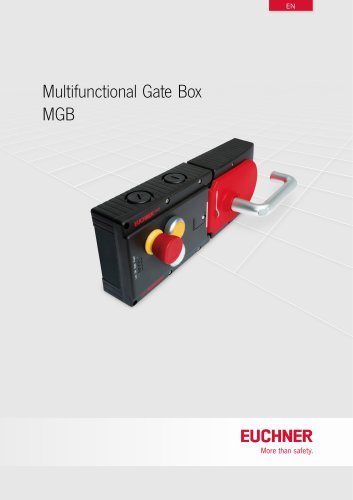 Multifunctional Gate Box MGB
137 Pages
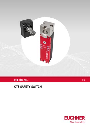 Safety switch CTS
8 Pages
 EUCHNER Safety Services
24 Pages
 Logistics
5 Pages
 IO-Link Safety
4 Pages
 News
News6 Pages
 Safety Relays ESM
32 Pages
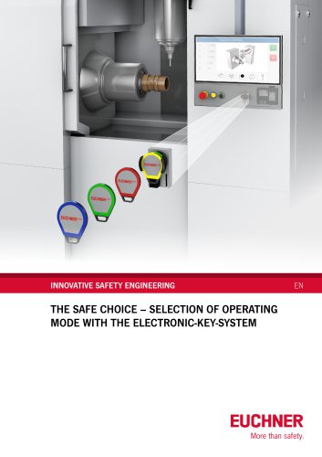
 Electronic-Key-System EKS2
6 Pages
 Safe key system CKS2
10 Pages
 Enabling Switches ZS
92 Pages
 About EUCHNER
34 Pages
 Safety Switches with Plastic Housing
172 Pages
 Safety Switches with Metal Housing
220 Pages
 Multiple Limit Switches
36 Pages
 Position Switches
56 Pages
 Safety Switches NQ/TQ
6 Pages
 Joystick Switches
28 Pages
 Electronic-Key-System
24 Pages


- Lumibird management software
- Lumibird single-pole switch
- Lumibird Windows software
- Lumibird mechanical lock
- Lumibird technology switch
- Interface software
- Lumibird multipole switch
- Visualization software solution
- Programming software
- Lumibird door lock
- Lumibird steel lock
- Lumibird electromechanical switch
- Rotary electric switch
- Lumibird limit switch
- Lumibird zinc lock
- Lumibird IP67 switch
- Lumibird safety lock
- Lumibird touch switch
- Lumibird light curtain