


Rotary cam switches

Rotary cam switches
Overview
The CS series rotary cam switches are engineered for versatile switching tasks in main and auxiliary electrical circuits, primarily targeting motor control applications such as direct-online starting/stopping, star-delta switching, reversing, and pole-change operations. They also support auxiliary functions including control, signaling, measurement circuits, resistor and heater group switching, and automatic return control switches.
Key Advantages
- High making and breaking capacities for reliable load switching.
- Robust electrical and mechanical endurance ensuring long service life.
- Compact design for easy integration into control panels.
Standards Compliance
The switches meet international and national standards: IEC/EN 60947-3, VDE 0660, TS EN 60947-3, and BS 5419, guaranteeing safety and interoperability.
Designation and Coding
Product codes follow the format: CS XX(Ith[A]) YY(diagram) Z_(design), where XX denotes thermal current rating, YY the switching diagram, and Z the design variant.
Switch Types and Configurations
- ON-OFF Switches: Basic 60° switching angle, available in 1 to 4 poles, current ratings from 10A to 100A.
- Multistep Switches: Multiple switching positions with 60° steps.
- Voltmeter and Ammeter Switches: 1 to 3 poles, some with transformer integration for measurement circuits.
- Changeover Switches: 1 to 3 poles, enabling switching between two circuits.
- Start and Run Switches: For single-phase motor control with 0-start-1 sequence.
- Star-Delta Switches: For motor starting using star and delta configurations.
- Motor Reversing Switches: 1-0-2 and L-0-P sequences for reversing motor direction.
- Emergency ON-OFF Switches (LK version): Padlockable in 'off' position, red handles with yellow background for safety compliance.
- Rotary Cam Switches in Insulated Enclosures: Protection ratings IP54 to IP65, grey color (RAL 7035), maintaining switching functions with enhanced environmental protection.
Technical Data Highlights
- Thermal current ratings from 10A to 100A and above.
- Weights range approximately from 75g to over 1000g depending on type and rating.
- Packaging typically includes one piece per package.
- Connection diagrams and switching layouts specify pole numbers and switching positions (e.g., 0-1, 0-1-2, 1-0-2).
Switching Diagrams and Pole Configurations
- 1-pole switches with positions like 0-1.
- 2-pole switches with positions such as 0-1 or 0-1-2.
- 3-pole and 4-pole switches with multiple switching steps.
- Switching scale typically 60° per step for precise control.
Applications and Recommendations
- Ideal for industrial motor control, auxiliary circuit switching, measurement instrumentation, and emergency stop functions.
- Compliance with international standards and availability in insulated enclosures make them suitable for harsh and safety-critical environments.
Summary of Critical Parameters
- Thermal Current (Ith): 10A to 100A and higher.
- Switching Angle: 60° per step.
- Poles: 1 to 4 poles.
- Protection Ratings: IP54 to IP65 for insulated enclosure variants.
- Weight: Approximately 75g to over 1000g.
- Standards: IEC/EN 60947-3, VDE 0660, TS EN 60947-3, BS 5419.
- Special Features: Padlocking for emergency switches, transformer integration for ammeter switches.
Rotary Cam Switches in Insulated Enclosures
1. Product Categories and Types
- Voltmeter Switches: 3-line, 3-phase, 16A to 40A thermal current.
- Motor Reversing Switches: L-0-P type, 16A to 40A.
- Multistep Switches: 3-pole, 60° switching angle, 16A to 40A.
- Star-Delta Switches: 0-star-delta configuration, 25A to 40A.
- Emergency ON-OFF Switches (LK version): For emergency control.
2. Technical Specifications
- Thermal current ranges from 10A to 40A depending on model.
- Available in 1 to 4 poles.
- 60° switching angles for multistep switches.
- Connection diagrams provided for installation guidance.
- Weights range from approximately 220g to 645g.
3. Product Codes and Layouts
Unique codes identify switch models, current ratings, and configurations, e.g., CS 16 67 PN 16A, CS 25 11 U L0PPN 25A, CS 40 12 PN2 40A, CS 32 90 PNGLK 32A.
4. Connection and Wiring Details
Connection diagrams illustrate pole arrangements and phase connections (L1, L2, L3, U, V, W). Motor reversing switches show L-0-P positions; multistep switches indicate pole and scale positions.
5. Application Notes and Recommendations
- Designed for insulated enclosure mounting for safety and reliability.
- Thermal current ratings must match application load to prevent overheating.
- Correct wiring per diagrams is essential for proper operation.
- Multistep switches enable precise multi-position control.
- Emergency ON-OFF switches allow rapid disconnection in critical situations.
6. Summary of Key Parameters
| Switch Type | Thermal Current (A) | Poles | Weight (g) | Typical Application |
|---|---|---|---|---|
| Voltmeter Switches | 16 - 40 | 3 | 220 - 560 | Voltage measurement switching |
| Motor Reversing Switches (L-0-P) | 16 - 40 | 3 | 265 - 560 | Motor direction control |
| Multistep Switches (60° angle) | 16 - 40 | 1 to 4 | 230 - 645 | Multi-position switching |
| Star-Delta Switches | 25 - 40 | 3 | Not specified | Motor starting method |
| Emergency ON-OFF Switches (LK version) | Not specified | Not specified | Not specified | Emergency control |
7. Limitations and Considerations
- Thermal current ratings must not be exceeded to avoid damage.
- Installation must follow connection diagrams to ensure safety and functionality.
- Weight and packaging details are important for logistics and handling.
Note: Additional technical data and connection diagrams are referenced for detailed installation and wiring instructions.
Catalog excerpts

Rotary cam switches series CS are intended for multiple switching operations in main as well as in auxiliary circuits: ■ As motor switches they are designed for direct-online starting and stopping of single- phase and three-phase motors. They also come out as star-delta switches, reversing switches, pole-change over motor switches. ■ In auxiliary circuits they are assembled in compliance with the switching programme according to preference: • switches for control, signalling and measuring circuits. • switches, selector switches and step switches e.g. for transformers and welding apparatuses. • Group switches e.g. for switching operations of resistors and heaters. • Control switch with automatic return Advantages ■ high making and breaking capacities ■ electrical and mechanical endurance ■ small dimensions. Rotary cam switches comply with international and national standards such as: IEC/EN 60947-3, VDE 0660,TS EN 60947-3, BS 5419 etc. Designation CS XX(Ith[A]) YY(diagram) Z_(design) Connection diagram in technical data 392 Technical data on page 423
Open the catalog to page 1
Connection diagram in technical data Technical data on page 423 393
Open the catalog to page 2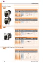
Ammeter Switches Thermal current 16 - 40 A Connection diagram in technical data Connection diagram in technical data 1 pole 3 current with transformer Connection diagram in technical data 2 pole 3 current with or without transformer Connection diagram in technical data Changeover Switches with 60 Switching Angle Thermal current 10 - 100 A Voltmeter Switches Connection diagram in technical data 394 Technical data on page 423
Open the catalog to page 3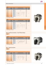
Technical data on page 423 395
Open the catalog to page 4
Rotary Cam Switches Motor Reversing Switches CS 25 91 U LK CS 32 91 U LK CS 40 91 U LK CS 63 91 U LK CS 80 91 U LK CS 100 91 U LK Connection diagram in technical data 396 Technical data on page 423
Open the catalog to page 5
CS 25 10 U LK CS 32 10 U LK CS 40 10 U LK CS 63 10 U LK CS 80 10 U LK CS 100 10 U LK Connection diagram in technical data Technical data on page 423 397
Open the catalog to page 6
Rotary Cam Switches in Insulated Enclosures Rotary cam switches in insulated enclosures with: - IP65 degree of protection (PN, PNG and PNG LK housing) - IP55 degree of protection (PN1 and PN2 housing) - IP54 degree of protection (PN3 and PN4 housing) Color of enclosures is grey (RAL 7035) Connection diagram in technical data Connection diagram in technical data Connection diagram ii technical data 398 Technical data on page 428
Open the catalog to page 7
Connection diagram in technical data Connection diagram in technical data Technical data on page 428 399
Open the catalog to page 8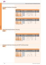
Rotary Cam Switches in Insulated Enclosures Connection diagram in technical data Connection diagram in technical data 400 Technical data on page 428
Open the catalog to page 9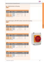
Rotary Cam Switches in Insulated Enclosures Connection diagram in technical data Technical data on page 428 401
Open the catalog to page 10All ETI catalogs and technical brochures
 VV/HH - High voltage fuse-links
10 Pages
 EFI eV
8 Pages
 RCCB-Btype
3 Pages
 GREEN PROTECT
84 Pages
 Special Purpose Fuses
82 Pages
 Battery Fuse
36 Pages
 Three-phase capacitors
8 Pages
 ETICONNECT
28 Pages
 PFC power factor controllers
4 Pages
 ETITEC : SURGE ARRESTERS
26 Pages
 ETITRAFO program
10 Pages
 Air circuit breakers
4 Pages
 ETIMETER program
6 Pages
 ETICONTROL program
4 Pages
 EVE program
92 Pages
 RCBO KZS-1M
2 Pages
 RCBO KZS 2M2p
8 Pages
 Miniature circuit breakers
16 Pages
 NH DC 1000V aR
1 Page
 C : Cylindrical fuse-links
2 Pages
 Low voltage fuse-links D
2 Pages
 Actuators and Indicators
10 Pages
 Change-over switches LAS
1 Page
 Switch disconnectors LA
2 Pages
 Switch disconnectors LAS
3 Pages
 VV : HIGH VOLTAGE FUSE-LINKS
10 Pages


Archived catalogs
 TECHNICAL CERAMICS
48 Pages
 TOOLS AND EQUIPMENT
8 Pages


- Rectangular housing
- Dry transformer
- Surge protector
- Plastic housing
- Single-pole switch
- Wall-mount box
- Junction block
- Push-button switch
- Switching relay
- DIN rail lightning arrester
- Capacitor
- Circuit breaker
- Technology switch
- Class II surge protector
- Isolator switch
- Current transformer
- Multipole switch
- Screw connection terminal block
- Electronic equipment enclosure