


- Company
- Products
- Catalogs
- News & Trends
- Exhibitions
Fine-Pitch Installation

Fine-Pitch Installation
- Temperature Setting: Install the ERSA PowerWell i-Tip in your i-Tool and set the temperature between 285°C (545°F) and 360°C (680°F), depending on whether the alloy is lead-free or not.
- Component Placement: Position the component and secure two opposing corner pins.
- Flux Application: Apply flux to the pins on all sides of the SMD. A No-Clean flux cream or an approved flux is recommended.
- Tip Preparation: Clean the entire front position of the ERSA PowerWell i-Tip, including the concave, using a damp or dry sponge. Fill the concave portion with solder wire slightly above the rim, ensuring not to overfill.
- Soldering Technique: Hold the i-Tool lightly and set the filled tip parallel to the PCB on the flat exterior portion of the pins. Slowly pull the ERSA PowerWell across the pins towards you. The design ensures joint integrity without guidance or pressure.
- Repeat Process: Repeat the cleaning and soldering steps for the remaining sides of the SMD. Remove flux residue if necessary.
- Note: The size of the soldering tip should match the foot length and pitch of the lead.
- i-CON single station (Order no. 0IC1000A)
- i-CON2 double station (Order no. 0IC2000A)
- ERSA PowerWell tips (Order no. 0102WDLF16, ...-23, ...-35)
- Vacuum pipette SMD-Vampir (Order no. 0SVP100)
- Vacuum pipette VAC-Pen (Order no. 0VP020)
- No-Clean flux core cream (Order no. 0FMKANC32-005)
- Solder wire (Order no. 010MM0250LF02)
- Flux remover set (Order no. 0FR200)
- No-Clean desoldering wick (Order no. 0WICKNC2.2/10 or 2.7/10)
Catalog excerpts
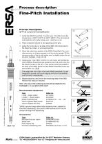
Process description Fine-Pitch Installation Process description 2 1 1. Install the ERSA PowerWell i-Tip in your i-Tool and set the temperature to 285°C (545°F) to 360°C (680°F). The set temperature depends on the alloy being used – lead free or not. 3 2. Place component and fix two opposing corner pins. 3. Apply flux to the pins on all sides of the SMD. We recommend a No-Clean flux cream, or your approved flux. 4. Clean the entire front position of the ERSA PowerWell i-Tip, including concave, on a damp sponge or on the dry tip sponge. Fill the concave portion of the tip with solder wire, to slightly above the rim. DO NOT OVERFILL THE TIP! 4 5. Holding your i-Tool VERY LIGHTLY in your hand, set the filled tip, with the ERSA PowerWell side parallel to the PCB, down onto the flat exterior portion of the pins. i-Tool and tip should be parallel to the body of the SMD. Slowly pull the ERSA PowerWell across the pins towards you. 5 6 3,5 PowerWell with concave portion The weight and form of the i-Tool and ERSA PowerWell i-Tip are designed to provide 100% joint integrity WITHOUT GUIDANCE and WITHOUT PRESSURE! 6. Repeat steps four and five for the remaining sides of the SMD. Remove flux residue if required. Note: The size of the soldering tip should be adapted to the 5 footlength L and pitch of the lead! © 11.2006 by ERSA, Wertheim, Germany • Subject to alterations Recommended equipment: Type i-CON – single station i-CON2* – double station ERSA PowerWell tips Vacuum pipette SMD-Vampir Vacuum pipette VAC-Pen *ERSA's product range offers further soldering irons, suitable for Fine-Pitch desoldering: Chip tool for SMD removal and X-Tool for standard through-hole desoldering. Accessories: ERSA i-Tool Type No-Clean flux core cream Solder wire Flux remover set No-Clean desoldering wick ERSA GmbH • Leonhard-Karl-Str. 24 • 97877 Wertheim • Germany Tel. +49 (0)9342/800-0 • Fax -127 • [email protected] • www.ersa.com
Open the catalog to page 1All Ersa GmbH catalogs and technical brochures
 Ersa wave soldering systems 2024
16 Pages
 X-TOOL VARIO
2 Pages
 SOLDERING TOOLS 2023/24
60 Pages
 Ersa MOBILE SCOPE
2 Pages
 REWORK- & INSPECTION SYSTEMS
44 Pages
 Particle Foam Machines
17 Pages
 Accessory Catalogue 2019
13 Pages
 VERSASCAN & VERSAEYE
5 Pages
 DISCOVER-SMART-TECHNOLOGIES
8 Pages
 Ersa Soldering Primer
32 Pages
 Ersa know-how transfer
2 Pages
 Ersa Catalogue
52 Pages
 Ersa VERSAPRINT 2
12 Pages
 Ersa HOTFLOW 4 Series
16 Pages
 Ersa HOTFLOW 3 Series
16 Pages
 Ersa MULTI WAVE
16 Pages
 Ersa VERSASCAN & VERSAEYE
8 Pages
 Ersa SERVICES
12 Pages
 Ersa Product Range
40 Pages


Archived catalogs
 Ersa wave soldering systems
16 Pages
 Ersa VERSAPRINT Stencil Printer
12 Pages
 Ersa SMARTFLOW 2020
8 Pages
 Ersa Festival of Innovations
8 Pages
 SOLUTIONS 4YOU
6 Pages
 Ersa CAD Assistant 3D
2 Pages


- Industrial robot
- Analysis software solution
- Process software
- Real-time software
- Windows software
- Computer-aided design software
- Articulated robot
- 6-axis robot
- Inspection system
- Interface software
- Visualization software solution
- Simulation software solution
- Automated software
- Programming software
- Screen printing machine
- Machine software
- Creation software
- Applications robot
- Automatic screen printing machine
- Camera inspection system