Catalog excerpts

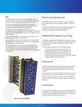
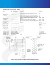
Test Block Applications that on connection of the ERMLB, the sockets on the even numbered side of the test plug are the isolated relay circuits and the sockets on the odd numbered side are connected to the potentially live supplies and shown in Figure 3. The ERMLG Test Block provides facilities for monitoring and secondary injection testing of any power system protection scheme, when used with the multi-fingered test plug type ERMLB. Description ERMLG Test Block removes the need to disturb protective system wiring for testing. It is housed within an Epsilon enclosure and has 14 pairs of spring loaded contacts which are linked to a terminal block positioned at the rear of the enclosure. Each pair of contacts are normally closed, completing the circuit through the test block when the associated protection equipment is in use. For testing purposes the test block can be accessed by removing the front cover. The ERMLG has a metallic probe attached to the front cover assembly which, when withdrawn, open circuits the 2 contacts at position 13 and 14. The main dc auxiliary supply to the protection scheme or relay can be wired to this circuit to prevent inadvertent tripping of the protection circuit after removal of the cover and during the test procedure. The short test finger in position 13-14 on the ERMLB will open contacts 13-14 in the test block after the other fingers have made contact in all other positions. When the cover is removed, a blue fascia is revealed which is attached to the test block. This gives a visual indication and warning that the protection scheme or relay is not in service. The insertion of the ERMLB test plug into the ERMLG assembly (as shown in Figures 1 and 2) open circuits the contact pairs. The ERMLB has 28 test points, each position being identified by a number which corresponds with the terminations on the ERMLG. It is recommended that the protection scheme or relay is wired to the even numbers of the test modules. To ensure the scheme wiring is routed logically, it is recommended that the ERMLG is always positioned on the right-hand side of the relay, when viewed from the front. The connections to other equipment such as CTs, VTs, and dc supplies should be made to the odd numbered terminals indicated on the ERMLG. This will ensure Figure 1: Test Block ERMLG
Open the catalog to page 1
Note: It is important that the sockets in the plug (ERMLB) which correspond to the current transformer’s secondary windings are linked prior to the plug being inserted into the test block. This will ensure that the current transformer’s secondary windings are short circuited prior to disconnection from the protection scheme or relay (as shown in Figure 3). Terminals 13 and 14 on ERMLG must not be used for CT connections since this will present a safety hazard. The reason for this that the associated ERMLB test plug contact finger is shorter than the others. If the dc auxiliary supply is to...
Open the catalog to page 2
Detailed Environmental Tests Test Type Test Description Insulation resistance test Test Points Test Level Between all case terminal connected together and case earth terminal Between all case terminal 13 and 14 (when the cover is opened) Between incoming and outgoing contacts when ERMLB is inserted Between all case terminal connected together and case earth terminal Between terminal 13 and 14 (when the cover is opened) Between incoming and outgoing contacts when ERMLB is inserted Between all case terminal connected together and case earth terminal Impulse voltage withstand Continuous...
Open the catalog to page 3
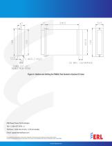
Figure 4: Outline and Drilling for ERMLG Test Socket in Epsilon E2 Case ERLPhase Power Technologies Tel: +1 204-477-0591 x 1 Toll Free: 1-833-502-2160 x 1 (US & Canada) Email: support@erlphase.com The specifications and product information contained in this document are subject to change without notice. In case of inconsistencies between documents, the version at www.erlphase.com will be considered correct. (D04252R02) Srinivas an D Digitally signed by Srinivasan D Date: 2023.08.01 10:16:23 +05'30'
Open the catalog to page 4All ERLPhase catalogs and technical brochures
-
TESLA Portable
2 Pages
-
T-PRO 4000
8 Pages
-
L-PRO
8 Pages
-
Multi Busbar Protection Relay
14 Pages
-
RecordBase Central Station
2 Pages
-
S-PRO 4000
9 Pages
-
L-PRO 4000
9 Pages
-
F-PRO
8 Pages
-
B-PRO 4000
8 Pages
-
TESLA LITE
5 Pages
-
TESLA 4000
8 Pages


