- Products
- Catalogs
- News & Trends
- Exhibitions
Spindle Lifting Systems
1 /32Pages

Spindle Lifting Systems
1 /32Pages
Catalog excerpts

Lifting Systems hydraulic and spindle lift systems English
Open the catalog to page 1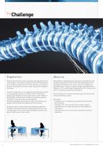
Physical discomfort such as backache and leg pains have a major impact on a person’s quality of life and consequently on a company’s performance. These ailments can lead to a decline in productivity, work of lower quality and extended sick leave. We have been developing and manufacturing hydraulic and spindle lifting systems since 1999. The lifting systems are available as lifting columns and in the form of table legs and table bases. They are used for height-adjustable work stations or for a wide range of applications. Our mission is to strive for quality, progress and reliability. The aim of...
Open the catalog to page 2
System configurator In the field of mechanical engineering, our products offer a cost-efficient and simple alternative to conventional drive systems. Assemble your very own lifting system at www.ergoswissconfig.com. Whether you need individual lifting elements or a complete base frame, all we need is a few clicks from you to configure a suitable product. We will then send you a personal quotation by e-mail. We offer you: – expert advice – nline configuration with automatic creation of a quotation o – apid response to requests for quotations r – hort lead times s – aultless after-sales service...
Open the catalog to page 3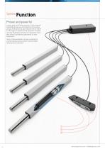
Proven and powerful Linear units and lifting columns (1) with integrated spindle drives are controlled synchronously using a control box (2) and manual control switch (3). All types of spindle lifting elements manufactured by Ergoswiss AG have an integrated motor that drives a spindle and generates a linear movement. Up to 4 lifting elements can be connected to a synchronous control system and smoothly retracted and extended.
Open the catalog to page 4
Some of the features of our spindle lifting systems: – Simple plug & play assembly and start-up. – Generous legroom and more design scope as the drive is installed directly in the lifting element. – No restoring force is required. Lifting element Cross section
Open the catalog to page 6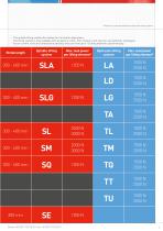
*Please also note the maximum load of the entire system – The spindle lifting system also allows for horizontal adjustment. – The lifting system is only available with an electric motor. (For a hand-crank solution, see hydraulic catalogue). – As our control units are connected in parallel, they can drive up to 12 lifting elements synchronously. Stroke length Spindle lifting system Max. load power per lifting element* Max. load power per lifting element* Hydraulic lifting system
Open the catalog to page 7
Combinations SLA|SLG|SQ|SE This table will help you to put together your own system on the basis of the required system load, the number of lifting element (linear units and lifting columns) to be activated and the desired lifting distance. Stroke length Lifting element type Control unit type Duty cycle** (on/off) Stroke length Lifting element type Control unit type Duty cycle** (on/off) Stroke length Lifting element type Control unit type Duty cycle** (on/off) Stroke length Lifting element type Control unit type Duty cycle** (on/off) Stroke length Lifting element type Control unit type Duty...
Open the catalog to page 8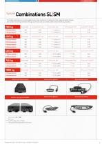
Combinations SL|SM This table will help you to put together your own system on the basis of the required system load, the number of lifting element (lifting columns) to be activated and the desired lifting distance. Stroke length Lifting element type Control unit type Duty cycle** (on/off) Stroke length Lifting element type Control unit type Duty cycle** (on/off) Stroke length Lifting element type Control unit type Duty cycle** (on/off) Stroke length Lifting element type Control unit type Duty cycle** (on/off) Stroke length Lifting element type Control unit type Duty cycle** (on/off) Control...
Open the catalog to page 9
Linear units SLA|SLG The housing of the linear unit consists of a colourless anodised aluminium profile. The stand pipe is made of stainless steel and positioned in a plastic bushing. It is operated by means of an internal spindle drive. The cable length is 2 metres. The linear units SLA and SLG are used in places where a work surface needs to be adjusted to the right ergonomic height. Existing work stations can simply be retrofitted. The systems fit perfectly into the 40x40 mm and 50x50 mm steel profiles which are often used as support elements and legs for work stations. Up to 4 linear units...
Open the catalog to page 10
Technical data - Versatile linear guide rail with internal drive unit - Compressive force per lifting element 1250 N (SLA/SLG) - Tensile force per lifting element 1250 N (SLA/SLG) - Please also note the maximum load of the entire system - Synchronous control of 1 to 8 linear units - Lifting speed 9 mm/s - Stroke length 300 or 400 mm - Mb stat. = 150 Nm* SLA SLG Mb stat. = 200 Nm* - Mb dyn. = 50 Nm** SLA SLG Mb dyn. = 80 Nm** - additional guide rail No is required - Colour: colourless anodised aluminium * stat. = max. permissible Mb bending moment at a standstill M ** b dyn. = max. permissible...
Open the catalog to page 11
Lifting column The lifting column SL consists of two colourless anodised aluminium profiles, guided by plastic gliders. Each lifting column has an internal motor that drives a threaded spindle. The cable length is 1.8 metres. The SL is available as a lifting system (lifting column and control unit) or as a complete base frame. The T-slots on 3 sides (width 8 mm) of the lifting column allow the addition of crossbars, shelves, attachments and mountings. Up to 3 lifting columns can be connected to one control unit. When a maximum of 4 control units are synchronised, up to 12 lifting columns can...
Open the catalog to page 12
Technical data - Versatile lifting column with internal drive unit - System loads: - 1 SL: 2000 N - 2 SL: 4000 N (6000 N) - 3 SL: 4000 N (7500 N) - 4 SL: (10000 N) - Synchronous control of 1 to 12 (8) lifting columns - Lifting speed 12 mm/s (8.5 mm/s)*** - Stroke length 300 or 400 mm - Mbx stat. = 450 Nm* Mby stat. = 1200 Nm* - Mbx dyn. = 200 Nm** Mby dyn. = 550 Nm** - Colour: colourless anodised aluminium * stat. = max. permissible Mb bending moment at a standstill M ** b dyn. = max. permissible bending moment during lifting movement L *** ifting speed load dependent Detailed CAD drawings in...
Open the catalog to page 13All ErgoSwiss catalogs and technical brochures
 Base frameSE
2 Pages
 Lifting columnSL
2 Pages
 Base frameSM
2 Pages
 TABLE BASE FC 650 3.0
1 Page
 Base frame TU
2 Pages
 Base frame TT
2 Pages
 Base frame TQ
2 Pages
 Base Frame TA
2 Pages
 Micro Hydraulics
48 Pages
 FB / FC series
2 Pages
 ST series
5 Pages
 SL series
5 Pages
 TL series
1 Page
 General Catalogue
48 Pages
 Fast and quiet
2 Pages
 Comfortably driven
2 Pages
 Compact power packs
2 Pages
Archived catalogs
 Quick Ship Systems
2 Pages
 Complete product catalogue
24 Pages
 System selection guide
1 Page
