HM2.0
1 /80Pages

HM2.0
1 /80Pages
Catalog excerpts

Hardmetric Connectors for Backplane-Systems
Open the catalog to page 1
Hardmetric Connectors: hm2.0 for Backplane-Systems
Open the catalog to page 2
Introduction Overview The Standard / High-Speed System Modularity Overview: CompactPCI Technical Specifications Electrical Characteristics Cross-Talk Hole Specifications Pin Lengths hm2.0 Type A hm2.0 Type B25 hm2.0 Type B22 hm2.0 Type B19 hm2.0 Type AB25 hm2.0 Type AB22 hm2.0 Type AB19 hm2.0 Type C hm2.0 Type D hm2.0 Type E hm2.0 Type DE hm2.0 Type F hm2.0 Type L hm2.0 Type M hm2.0 Type N Accessories: Shroud Accessories: Coding Keys
Open the catalog to page 3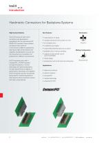
Hardmetric Connectors for Backplane-Systems High Contact Density The hm2.0 series of hard metric connectors was developed in accordance with the international IEC 61076-4-101 standard. These shielded connectors have a pitch of 2 mm and are suitable for applications that require high contact density and reliability. Standardization ensures that the connectors are compatible with products from different manufacturers. • wide selection of types • modular connectors with a pitch of 2 mm • 5 or 8 signal rows • 12 different pin lengths • customized assembly layout as an option • available with or without...
Open the catalog to page 4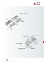
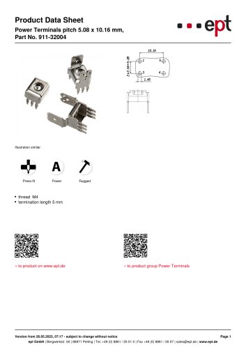
Type A Female Connector press-fit zone Tcom press® internal spring contact with or without shield 2 mm pitch Type A Male Connector outside contact rows for shielding PBT 5 internal contact rows for signal transmission press-fit zone Tcom press®
Open the catalog to page 5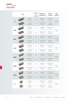
of contacts A Male connector A A Female connector B25 Male connector B25 B25 Female connector B22 Male connector B22 B22 Female connector B19 Male connector B19 B19 Female connector AB25 Male connector AB25 AB25 Female connector AB22 Male connector AB22 AB22 Female connector AB19 Male connector AB19 AB19 Female connector C Male connector
Open the catalog to page 6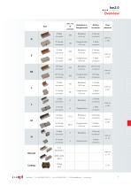
of contacts D Male connector D D Female connector E Male connector E E Female connector DE Male connector DE DE Female connector F Male connector F F Female connector L Male connector connector M Male connector connector N Male connector Coding keys
Open the catalog to page 7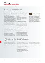
The Standard IEC 61076-4-101 The hardmetric connector system ept hm2.0 was developed and manufactured according to the international standard IEC 61076-4-101. Thus the user can rely on a worldwide standard for the connection of printed circuit boards using connectors with a large number of contacts. The printed circuit boards can be exchanged between systems without difficulty. Important parameters such as the fixing, shielding and coding of the printed circuit boards are compatible regardless of the individual application. ept hm2.0 connectors are designed with a 2 mm metric grid. They can be...
Open the catalog to page 8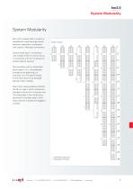
System Modularity ept hm2.0 modules offer a number of possibilities to optimize large contact densities, especially in combination with coaxial or fiber-optic connections. Anzahl Kontakte: Number of contacts: 110 Using module type A, connections with a length of 50 mm can be set up in increments of 25 mm to achieve an overall length as required. The connectors with a multifunction block (types A, M, L) are preferably arranged at the beginning of a connector row. The type B module on the other hand is only arranged between other modules. Due to their inverse-polarity protection the 25 mm type...
Open the catalog to page 9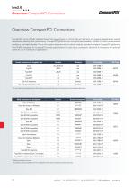
hm2.0 Overview CompactPCI Connectors Overview CompactPCI Connectors CompactPCI as the PICMG standard places high requirements on 19-inch high-end systems with passive backplanes as regards robustness, reliability, and performance. CompactPCI platforms are cost optimized, scalable, suitable for harsh environmental conditions, and highly durable. This is why system designers rely on robust, modular, standard-compliant CompactPCI platforms. The PICMG® standards for CompactPCI provide specifications for hard metric connectors. ept’s hm2.0 connectors are optimally suited for use in CompactPCI applications....
Open the catalog to page 10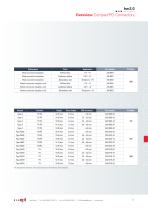
hm2.0 Overview CompactPCI Connectors Coding keys Part number Male connector backplane Brilliant blue Male connector backplane Cadmium yellow Male connector backplane Female connector daughter card Brilliant blue Female connector daughter card Cadmium yellow Female connector daughter card Base height The height/bottom thickness of the shroud depends on the thickness of the backplane.
Open the catalog to page 11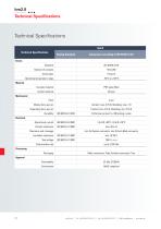
Technical Specifications hm2.0 Technical Specifications Testing Standard Basics Standard Operating temperature range Insulator material Contact material Mechanical Pitch Performance level II = 250 mating cycles Operational current Contact resistance min. 0.6 Female connector, min. 0.8 mm Male connector Insulation resistance Test voltage Data transfer rate Processing Packaging Male connectors: Tube; Female connectors: Tray RoHS compliant
Open the catalog to page 12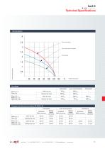
Derating diagram Chess board pattern Every second position equipped . Fully equipped Current carrying capacity Ambient temperature Test voltage Rows a, c, e Rows b, d Rows a, b, c Rows a, b, c, d Rows a, b, c, d, e Fully loaded every second position Creepages and clearances according to IEC 61076-4-101 Fully loaded Rows a, c, e Rows b, d Rows a, b, c Rows a, b, c, d Rows a, b, c, d, e every second position Backplane Male connector Module Female connector Backplane Male connector Module Female connector Backplane Male connector Module Female connector
Open the catalog to page 13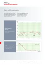
Electrical Characteristics The connector system ept hm2.0 has been especially developed for high data rates. Below some HF characteristics are described as example. A SPICE model is available for simulation when developing systems. The simulation model was verified by means of TDR measurements. Impedance gradient along a pin in row d Impedance measured after eliminating multiple reflection Female connector Soldered connection Male connector Soldered connection Ureflect_max is the maximum reflection of an ept hm2.0 connector in percent, shown as function of the signal rise time. The connector...
Open the catalog to page 14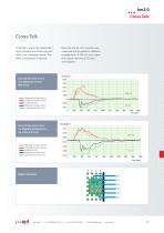
Cross Talk ‘Crosstalk’ means that independent signal channels are influencing each other in an unwanted manner. This effect is expressed in decibels. Near end and far end cross talk was measured and simulated for different arrangements. A 200 mV input signal and a signal rise time of 25 psec. were applied. Cross talk from a pin in row d to an adjacent pin in row d (from C to G) Near end Measured cross talk, near end Simulated cross talk, near end Background noise Measured cross talk, far end Simulated cross talk, far end Cross talk from a pin in row d to a diagonally positioned pin in row e (from...
Open the catalog to page 15All Ept catalogs and technical brochures
 ZERO8
ZERO816 Pages
 COLIBRI®
16 Pages
 Connectors product catalog no. 27
377 Pages
 One27 Connectors
28 Pages
 Connectors product overview
28 Pages
 406-52112-51
5 Pages
 406-52120-51
5 Pages
 501-50096-183
5 Pages
 962-40202-03
3 Pages
 405-54152-51
5 Pages
 405-54180-51
5 Pages
 405-55112-51
4 Pages
 405-55120-51
4 Pages
 405-55132-51
4 Pages
 405-55152-51
4 Pages
 405-55180-51
4 Pages
 405-53120-51
5 Pages
 405-52180-51
5 Pages
 405-52152-51
5 Pages
 405-52132-51
5 Pages
 405-52120-51
5 Pages
 990-52XNN250-110
5 Pages
 990-52XNN200-110
5 Pages
 990-52XNN150-110
5 Pages
 990-52XNN100-110
5 Pages


- Data connector
- Electrical power supply connector
- Metal connector
- Polymer connector
- Junction block
- Rectangular connector
- Solderless terminal
- Current connector
- Straight connector
- Copper connector
- Cable assembly
- DIN connector
- Plug-in connector
- Right-angle electrical connector
- IEC connector
- SMT connector
- Plug connector