

- Products
- Catalogs
- News & Trends
- Exhibitions
FIN900 Three Phase Choke

FIN900 Three Phase Choke
Catalog excerpts
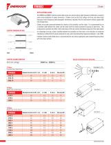
APPLICATION GUIDE The FIN900 and FIN930 common mode choke series are used to reduce high frequency interference caused by pulse wave modulation of power transistors. Chokes round out the fast voltage rise time and reduce high frequency (radio frequency) electromagnetic interference radiated into the environment without appreciable line voltage drops. Chokes are usually connected between the inverter, or the controller, and the motor. It is recommended to run a shielded cable between the choke and the motor with the shield connected to ground at both ends. This configuration combines the effect of the inductance of the coil and the distributed capacity of the cable shield. An advantage to using a choke installed between the controller and the motor is the reduction of conducted interference emitted from the device towards the main and characterized by frequencies between 1 and 3 MHz. Enerdoor common mode choke series is recommended for servo drive applications and variable frequency drives with close loop systems. ELECTRIC CHARACTERISTICS Electric And Mechanical Assembly Nominal voltage 3-Phase Cylindrical Case / Cable Output Metallic Case / Cable Output 3-Phase Metallic Case / Screw Output MOTOR PROTECTION
Open the catalog to page 1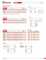
MECHANICAL DIMENSIONS (mm) CYLINDRICAL CASE Available in 2C version with cable lengths (H) in 400 or 600 mm METALLIC CASE METALLIC CASE CONNECTION Line Ground d (mm) Torque (Nm) d1(mm) Torque (Nm) M4 1.2 M4 1.2 M5 MOTOR PROTECTION
Open the catalog to page 2All ENERDOOR catalogs and technical brochures
 E 3746
2 Pages
 FINHRMA
2 Pages
 FIN1520.0V
4 Pages
 FIN1520
4 Pages
 FIN1220.0V
4 Pages
 FIN7212
4 Pages
 FINFF Line Reactor 3%
1 Page
 FIN1220 DC Filter
2 Pages


- Electronic filter
- Passive electronic filter
- AC electronic filter
- Low-pass electronic filter
- Three-phase electronic filter
- EMI filter
- Compact electronic filter
- Single-phase electronic filter
- High-pass electronic filter
- RFI electronic filter
- Power electronic filter
- Motor electronic filter
- Harmonic filter reactor
- Sine wave electronic filter
- DIN rail electronic filter
- Common mode electronic filter
- Electronic filter for medical applications