- Catalogs
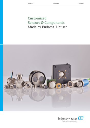
- Endress+Hauser Sensors & Components
- Technical Information - Radar module UTR30

- Products
- Catalogs
- News & Trends
- Exhibitions
Technical Information - Radar module UTR30
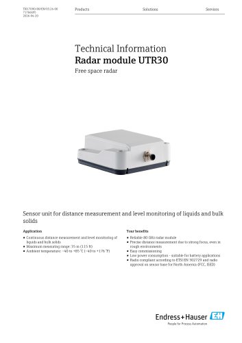
Technical Information - Radar module UTR30
The document details the Radar module UTR30, a sensor for continuous distance measurement and level monitoring of liquids and bulk solids. It covers applications, benefits, and compliance with radio standards.
- Measuring Range: Up to 35 m (115 ft) for liquids and bulk solids.
- Operating Frequency: 80 GHz.
- Ambient Temperature: -40 to +85 °C (-40 to +176 °F).
- Output Signal: Options include UART and RS422.
- Power Supply: Requires two supply voltages with specific ranges for sensor and digital interface.
The UTR30 uses the time-of-flight method (ToF) and Frequency Modulated Continuous Wave (FMCW) principle for distance measurement, suitable for non-conductive tank walls.
- Accuracy: Varies based on distance and medium type, with specific error margins for liquids and solids.
- Temperature Influence: Temperature coefficient is ≤ 4 mm per 10 K.
- Protection Degree: IP66/68 for plastic enclosure, IP00 for base plate.
- Pollution Degree: 3 according to IEC/EN 61010-1.
The module is available in a plastic enclosure or mounted on a base plate, with specific dimensions and weight details.
Includes safety notes, positioning guidelines, and beam angle considerations to avoid interference signals.
The module complies with RoHS, ETSI EN 302 729, FCC, and Industry Canada standards.
Details on mechanical/electrical integration, configuration, and control via digital interfaces are provided, emphasizing the need for a closed housing and unobstructed signal cone.
The document outlines specifications for the radar module UTR30, including dimensions and measuring distances. It emphasizes using a compatible connector with a locking mechanism and performing a functional check and zero offset calibration after installation.
Diameter and measuring distances are provided in a table, with beam angles specified at 8°. The radar module is designed for specific installation conditions, including a fixed vertical downward position and distance requirements from astronomy stations.
The UTR30 module complies with various directives and standards, including RoHS, ETSI EN 302 729, and FCC Part 15. It requires professional installation and adherence to specific conditions to avoid interference with radio astronomy stations.
Installation must be performed by trained personnel, following detailed instructions. The module must be installed at a specified distance from astronomy stations, with height restrictions in certain areas.
The module is part of a system requiring customer-obtained approvals. It complies with EN 61010-1 for safety and carries a CE mark, indicating conformity with EU directives.
The document includes disposal instructions in line with the WEEE directive and provides contact information for further assistance.
Catalog excerpts
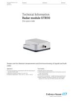
Technical Information Sensor unit for distance measurement and level monitoring of liquids and bulk solidsApplication ■ Continuous distance measurement and level monitoring of liquids and bulk solids ■ Maximum measuring range: 35 m (115 ft) Your benefits ■ Reliable 80 GHz radar module ■ Precise distance measurement due to strong focus, even in rough environments ■ Low power consumption - suitable for battery applications ■ Radio compliant according to ETSI EN 302729 and radio approval on sensor base for North America (FCC, ISED) People for Process Automation
Open the catalog to page 1
Table of contents About this document . . . . . . . . . . . . . . . . . . . . . . . . . . . .3 Document function . . . . . . . . . . . . . . . . . . . . . . . . . . . . . . . . . . . . 3 Symbols used . . . . . . . . . . . . . . . . . . . . . . . . . . . . . . . . . . . . . . . . . 3 Disposal . . . . . . . . . . . . . . . . . . . . . . . . . . . . . . . . . . . . . . . . . . . . . 15 Contact addresses . . . . . . . . . . . . . . . . . . . . . . . . . . . . . . . . . . . . 15 Function and input parameters . . . . . . . . . . . . . . . . . . .4 Measuring principle . . . . . . . . . . . . . . . ....
Open the catalog to page 2
About this document Document function This document contains all the technical data for the device and provides an overview of the device versions that can be ordered, which may differ, for example, in their mechanical design or output signal. This symbol contains information on procedures and other facts which do not result in personal injury. Symbols for certain types of information
Open the catalog to page 3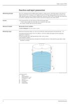
Measuring principle The core component of the UTR30 radar module is a radar sensor, operating based on the time-of- flight method (ToF). It measures the distance from the reference point to the product surface. The radar signals based on the "Frequency Modulated Continuous Wave" (FMCW) principle are emitted by an antenna, reflected off the product surface and received again by the radar system. Process ■ The measurement can be carried out directly through tanks -> This is only possible for electrically non-conductive tank walls No contact is made with the process medium. Measured variable Measured...
Open the catalog to page 4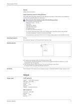
Medium Media: solids and liquids The usable measuring range depends on the reflection properties of the medium, the installation position and possible interference reflections. Measurement of the following media with absorbing gas phase For example the following media ■ Methyl ethyl ketone ■ VCM (vinyl chloride monomer) To measure absorbing gases, either use a guided radar, measuring devices with another measuring frequency or another measuring principle. If measurements must be performed in one of these media, please contact Endress+Hauser. The operating frequency is for measurement purposes...
Open the catalog to page 5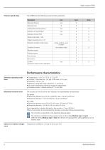
Protocol-specific data The UTR30 has the following read and write parameters: Reference operating conditions Maximum measured error Pressure = 960 mbar abs. (14 psi) ±100 mbar (±1.45 psi) Humidity = 60 % ± 5 % Reflector: metal plate with a diameter > 1m (40in) No major interference reflections inside the signal beam Frequency mode 1: default setting of 77 to 81 GHz The accuracy is the sum of the non-linearity, non-repeatability and hysteresis. For liquids: Non-repeatability is already included in the accuracy < 1 mm (0.04 in). Offset or zero point can be eliminated by entering a correction during...
Open the catalog to page 6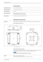
Environment Ambient temperature Storage temperature Relative humidity IP66/68 (Radar module in plastic enclosure) IP00 (Radar module mounted on base plate) Pollution degree Pollution degree 3 according to IEC/EN 61010-1 Mechanical construction Dimensions The radar module is available in a plastic enclosure and mounted on a base plate (without cover). Radar module in plastic enclosure Ansicht von unten View from below Radar module mounted on base plate The dimensions of the base plate can be seen in the previous drawings of the plastic enclosure. Further information on the geometry of the inside...
Open the catalog to page 7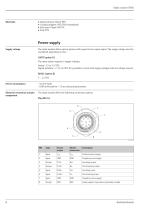
Materials ■ Radar antenna: Plastic PBT ■ Coupling adapter: PPS GF40 (metallized) ■ Enclosure: Plastic PBT/PC • Seal: TPE Supply voltage The radar module offers various options with regard to the output signal. The supply voltage must be considered depending on this. The radar system requires 2 supply voltages: Digital interface: 1.7 to 3.6 VDC (It is possible to cover both supply voltages with one voltage source). Power consumption ~32 mW static ~1000mW peak for <10ms during measurement Electrical connection and pin The radar module offers the following connection options:
Open the catalog to page 8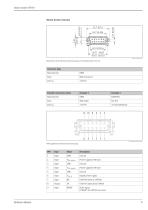
Mount header 2x6 pins Connector plug
Open the catalog to page 9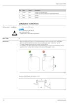
Installation instructions Safety notes for installation For work on and with the device: Static sensitive devices. ► Handle only at static safe work stations! Beam angle Positioning ■ Mount the measuring device in a horizontal position so that it is parallel to the tank ceiling. Otherwise, undesired reflections from the surroundings can cause interference signals. ■ The radar antenna should never be covered by metal objects. ■ Do not mount any objects which may cause interference, such as tank internal fittings, grids or agitators, below or in the direct vicinity of the radar (see the graphic...
Open the catalog to page 10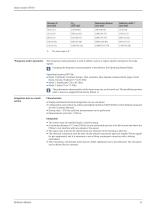
"Frequency mode" parameter The frequency mode parameter is used to define country or region-specific settings for the radar Changing the frequency mode parameter is described in the Operating Manual Radar. ■ Mode 1 (Default): Continent Europe, USA, Australia, New Zealand, Canada, Brazil, Japan, South Korea, Taiwan, Thailand (77 to 81 GHz) The performance characteristics of the device may vary on the mode set. The specified properties refer to device as supplied from factory (Mode 1). Simple mechanical/electrical integration into an end device Configuration and control via widely used digital...
Open the catalog to page 11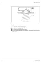
Check list • Is the radar module undamaged (visual inspection)? • Is the sensor properly mounted and fixed in position? • Is the antenna and enclosure properly sealed? • Is the sensor signal cone unobstructed? • Is the electrical connector properly fitted and locked? • Is the sensor responsive and returns a correct measurement value without any communication errors or active error bits?
Open the catalog to page 12