
- Catalogs
- Endress+Hauser Sensors & Components
- Technical Information - Ceracore UTC30


Technical Information - Ceracore UTC30
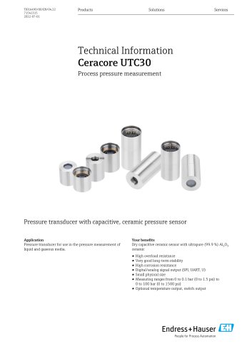
Technical Information - Ceracore UTC30
The Ceracore UTC30 is a pressure transducer designed for measuring the pressure of liquid and gaseous media. It features a capacitive ceramic sensor made from ultrapure aluminum oxide, offering high overload resistance, long-term stability, and corrosion resistance. The device supports both digital and analog signal outputs and offers optional temperature and switch outputs.
The UTC30 operates within a measuring range from 0 to 0.1 bar up to 100 bar. It uses a dry capacitive ceramic sensor, enhancing measurement accuracy by eliminating the need for a separating diaphragm or oil filling. The supply voltage ranges from 4.9 to 5.1 V DC, with digital output supply voltage between 2.9 and 5.5 V DC. It offers long-term stability of ≤ 0.1%/year related to the upper range limit.
The core component is a capacitive ceramic sensor element using a plate capacitor to measure pressure changes, providing high resolution and reproducibility. The sensor is available in gauge and absolute pressure types, each with specific configurations.
The device measures gauge or absolute pressure and temperature, featuring a digital-to-analog converter for output signals based on NAMUR NE 43 standards. It supports communication modes including UART and SPI.
The UTC30 requires a supply voltage between 2.9 and 5.5 V DC, with current consumption varying based on connection type. Proper polarity is essential to prevent damage.
Operating under reference conditions as per DIN EN IEC 62828, the device offers customizable damping settings and optional noise filtering.
Installation conditions, including position and environmental factors, are detailed. The device is designed to withstand vibration and offers overvoltage protection.
The UTC30 complies with the RoHS directive and the Pressure Equipment Directive 2014/68/EU. It adheres to additional standards and guidelines.
Details on calibration, service, and ordering information are provided, along with contact addresses for support. Calibration certificates are available on request, and the device complies with the WEEE directive for disposal.
Catalog excerpts
Technical Information Pressure transducer with capacitive, ceramic pressure sensor Application Your benefits Pressure transducer for use in the pressure measurement of Dry capacitive ceramic sensor with ultrapure (99.9 %) Al2O3 liquid and gaseous media. ceramic ■ High overload resistance ■ Very good long-term stability ■ High corrosion resistance ■ Digital/analog signal output (SPI, UART, U) ■ Small physical size ■ Measuring ranges from 0 to 0.1 bar (0 to 1.5 psi) to 0 to 100 bar (0 to 1500 psi) ■ Optional temperature output, switch output People for Process Automation
Open the catalog to page 1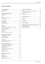
Table of contents About this document . . . . . . . . . . . . . . . . . . . . . . . . . . . .3 Document function . . . . . . . . . . . . . . . . . . . . . . . . . . . . . . . . . . . . 3 Symbols used . . . . . . . . . . . . . . . . . . . . . . . . . . . . . . . . . . . . . . . . . 3 RoHS . . . . . . . . . . . . . . . . . . . . . . . . . . . . . . . . . . . . . . . . . . . . . . . Pressure Equipment Directive 2014/68/EU (PED) . . . . . . . . . Other standards and guidelines . . . . . . . . . . . . . . . . . . . . . . . . . Calibration; unit . . . . . . . . . . . . . . . . . . . . . . . . . . ....
Open the catalog to page 2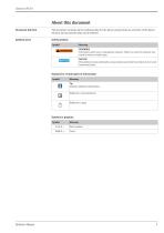
About this document Document function This document contains all the technical data for the device and provides an overview of the device versions and accessories that can be ordered. Symbols used Safety symbols
Open the catalog to page 3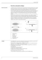
Function and system design Measuring principle A capacitive ceramic sensor element is at the core of the UTC30. The basic material is (Al2O3), an ultrapure (99.9%) aluminum oxide ceramic that is highly resistant to many aggressive gases and liquids. Two cylindrical ceramic components (process isolating diaphragm and ceramic substrate) are hermetically sealed together. In the case of absolute pressure sensors, the reference vacuum of 3.0 x 10⁻⁶ mbar that is generated in the production process between the process isolating diaphragm and the ceramic substrate becomes permanent, thereby enabling...
Open the catalog to page 4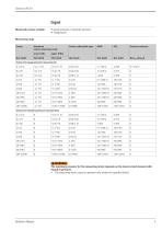
Measured process variable ■ Gauge pressure or absolute pressure Measuring range The maximum pressure for the measuring device depends on the lowest-rated element with regard to pressure. ► The measuring device must be operated only within the specified limits!
Open the catalog to page 5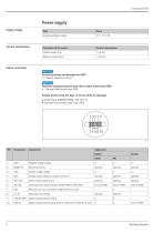
Current consumption Sensor connection NOTICE Incorrect polarity can damage the ASIC! ► Ensure polarity is correct. Incorrect analog measured value due to cable break from GND! ► Prevent cable break from GND. Female header strip 2x5 pins (1.27 mm (0.05 in) spacing) • Socket type: SAMTEC SFML-105-02-L-D ■ Insertion force (axial only): max. 40 N
Open the catalog to page 6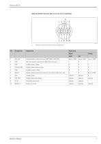
Male pin header strip 2x5 pins (2.54 mm (0.1 in) spacing) Reference air tube for orientation of the pin assignement Application Digital Communication mode selection (UART "GND" or SPI "VDD") SPI clock, must be connected to GND if SPI is not used Positive supply voltage Digital communication output Negative supply voltage Digital communication input, must be connected to GND if not used Analog output Switch output (open drain) Chip select (low active)
Open the catalog to page 7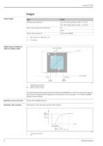
Output signal Output Type Signal range and signal on alarm of voltage output 1 Calibrated measuring range 2 Extended measuring range DAC Digital-to-analog converter The signal range and the signal on alarm are based on NAMUR NE 43. The error value of the signal on alarm can be configured and is displayed in the illustration for the example > 95 % VDD (CARMEN standard sensor setting). Behavior in case of an error See the S&C CARMEN Manual Dead time, time constant Presentation of the dead time and the time constant:
Open the catalog to page 8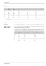
Dynamic behavior
Open the catalog to page 9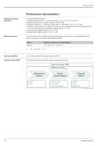
Reference operating conditions ■ Ambient temperature TA = constant, in range: +23 to +27 °C (+73 to +81 °F) ■ Relative humidity 9 = constant, in range: 5 to 80 % RH. ■ Ambient pressure pA = constant, in range: 860 to 1 060 mbar (12.47 to 15.37 psi) ■ Position of measuring cell = constant, in range: process isolating diaphragm pointing downwards (see also the "Influence of installation position" section ^ S 12) ■ Analog output supply voltage: 4.9 to 5.1 V DC ■ Digital output supply voltage: 2.9 to 5.5 VDC Reference accuracy The reference accuracy includes the terminal-based non-linearity, the...
Open the catalog to page 10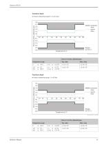
Total Error Band ■ Sensor measuring range: 0.1 to 0.4 bar
Open the catalog to page 11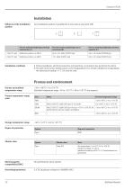
Influence of the installation Any installation position is possible but it may cause a zero point shift. Climate class Electromagnetic No specifications (open system) Overvoltage protection 6 V DC (maximum voltage for CARMEN ASIC)
Open the catalog to page 12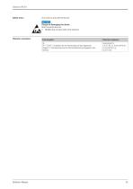
Safety notes For work on and with the device: Static sensitive devices. ► Handle only at static safe work stations! Test standard
Open the catalog to page 13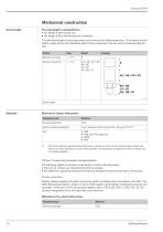
Device height The total height is calculated from • the height of the individual process connection. The individual heights of the components can be found in the following sections. To calculate the total height, simply add up the individual heights of the components. You can use the following table for this: Electronics housing Process connections Device height Materials Materials in contact with process
Open the catalog to page 14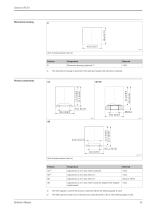
Electronics housing 1) The electronics housing is mounted if the male pin header strip 2x5 pins is selected. The "AA" capsule is used if the process connection KB on the following page is used. The "AB" capsule is used if one of the process connections BA to DC on the following page is used.
Open the catalog to page 15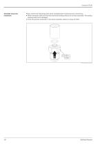
Assembly of process connection Please observe the following points when assembling the enclosed process connections: • Before assembly, make sure that the seal and all sealing surfaces are as clean as possible. The sealing surfaces must not be damaged. • Screw the process connection to the sensor assembly, observe a torque of 6 Nm.
Open the catalog to page 18
Certificates and approvals RoHS The measuring system complies with the substance restrictions of the Restriction on Hazardous Substances Directive 2011/65/EU. Pressure Equipment Directive 2014/68/EU (PED) Pressure equipment with allowable pressure ≤ 200 bar (2900 psi) Pressure equipment (with a maximum allowable pressure PS ≤ 200 bar (2900 psi)) can be classified as pressure accessories in accordance with Pressure Equipment Directive 2014/68/EU. If the maximum allowable pressure is ≤ 200 bar (2900 psi) and the pressurized volume of the pressure equipment is ≤ 0.1 l, the pressure equipment is...
Open the catalog to page 19All Endress+Hauser Sensors & Components catalogs and technical brochures
- Level probe
- Liquid level sensor
- Membrane pressure sensor
- Digital output level sensor
- Analog pressure sensor
- Vessel level sensor
- Stainless steel pressure sensor
- Relative pressure sensor
- Analog pressure transducer
- IP68 level sensor
- Gas pressure sensor
- Sensitive element pressure sensor
- Liquid pressure sensor
- Membrane pressure transducer
- Solid level sensor
- Digital pressure sensor
- Precision pressure sensor