
- Catalogs
- Endress+Hauser AG
- Prosonic S FDU91


Prosonic S FDU91

Prosonic S FDU91
The document provides detailed technical information on the Prosonic S FDU90/91/91F/92/93/95/96 ultrasonic sensors by Endress+Hauser. These sensors are designed for non-contact continuous level and flow measurement and are compatible with FMU90 and FMU95 transmitters. They are suitable for various applications, including fluids, pastes, sludges, and bulk materials.
- Continuous, non-contact level measurement for various materials.
- Flow measurement in open channels and measuring weirs.
- Maximum measuring ranges vary by model, with FDU96 reaching up to 70 m in bulk materials.
- Suitable for explosion hazardous areas.
- Non-contact measurement reduces service needs.
- Integrated temperature sensor for accurate time-of-flight correction.
- Hermetically welded PVDF sensors for chemical resistance.
- Automatic sensor detection for easy commissioning.
- Can be installed up to 300 m from the transmitter.
- Weather resistant and flood-proof (IP68).
- Dust-Ex and Gas-Ex certifications available.
Measuring Principle: Utilizes the time-of-flight method where ultrasonic pulses are transmitted and reflected back to measure distance.
Time-of-Flight Correction: Compensates for temperature-dependent changes using an integrated temperature sensor.
Blocking Distance: Level measurement must not extend into the blocking distance to ensure reliability.
Input: Measuring range depends on operating conditions and attenuation factors such as surface type and dust.
Operating Frequency: Varies by sensor model, e.g., FDU90 operates at 90 kHz.
Output: Signal transmission via analogue voltages.
Power Supply: Supplied by the FMU90 transmitter; optional sensor heater available for FDU91.
- Detailed connection diagrams and hints provided to avoid interference.
- Extension cables recommended for distances over 30 m.
- Installation options include flush mounting and nozzle installation.
- Ingress protection, vibration resistance, and thermal shock resistance are specified.
- Suitable for various environmental conditions with specific storage and process temperature guidelines.
- CE mark and Ex approval details provided.
- Compliance with external standards and guidelines.
- Detailed product structure and ordering information for each sensor model.
- Various accessories available, including extension cables, protective covers, and mounting brackets.
- Includes technical information, operating instructions, and safety instructions for the FMU90 transmitter.
The document outlines the specifications for sensor cables used with Prosonic S FDU90/91/91F/92/93/95/96 models. The cables can be up to 300 meters long with a cross-section ranging from 0.75 mm² to 2.5 mm². Each core can have a resistance of up to 8 Ω and a maximum capacitance of 60 nF between the core and screen. The earth lead must not be within the screening for certain models.
The sensor cables can be shortened if necessary, ensuring not to damage the cores. The metallic braiding serves as a return cable and should be securely twisted and connected to the "BK" terminal after shortening. The protective earth conductor should not be electrically connected to the cable shield. Various installation options are provided, including ceiling mounting and using cantilevers or wall brackets. The sensor membrane must not be damaged during installation.
For level measurements, sensors should be installed so that their lower edge projects into the vessel, avoiding the blocking distance. They should not be installed in the middle of the tank and should be aligned vertically to the product surface. For flow measurements, sensors should be installed at the inflow side above the maximum water level plus the blocking distance. Protective covers are recommended to shield sensors from direct sun or rain.
The FDU91F sensor can be flush mounted using a FAU80 slip-on flange. Flanges in polypropylene should only be used with pressures up to 1.5 barabs, while 316L flanges can handle higher pressures. The process seal is not included in the delivery.
Sensors are tested for ingress protection according to IP68/NEMA6P standards and have specific vibration and thermal shock resistance. They are compatible with electromagnetic standards and have defined process temperature and pressure ranges. For example, the FDU90 operates between -40 to +80 °C and 0.7 to 4 bar.
The document provides detailed dimensions for various sensor models, including FDU90, FDU91, FDU91F, FDU92, FDU93, FDU95, and FDU96. It also specifies the weight of each sensor model, with FDU96 being the heaviest at approximately 5 kg.
The sensor housing materials vary by model, with options including PVDF and 316L stainless steel. Other components like counter nuts and cable glands are made from materials such as PA6.6 and CuZn nickel-plated.
This document provides technical specifications, installation guidelines, and safety instructions for the Prosonic S series sensors (FDU90/91/91F/92/93/95/96) by Endress+Hauser. It includes details on chemical compatibility, cable connections, and product structure.
The sensors are made from various materials such as unsaturated polyester resin, CuZn nickel-plated components, and VMQ O-rings. Cable lengths range from 5 to 300 meters, with recommendations for extension cables if exceeding 30 meters. The document outlines different sensor models and their specific materials and coatings, such as 316L and PFA.
The sensors comply with EC guidelines and have CE marks. They are approved for use in hazardous environments with specific Ex documentation. Compliance with national and local standards is mandatory, and only qualified personnel should handle installations.
Sensors can be installed in various positions, including tanks and open channels. The document emphasizes the importance of ensuring safety and proper installation to avoid hazards.
The document references standards like EN 60529 for housing protection and EN 61326 for EMC compliance.
Detailed product structures for each sensor model are provided, including approval types, process connections, cable lengths, and additional options like heaters and linearity protocols.
This option involves testing the sensor's linearity across its measuring range. Specific calibration points must be defined, and the protocol is valid for the sensor-transmitter combination.
Extension cables and protective covers are available for different sensor models. Specifications for screw-in flanges and flooding protection tubes are also included.
The document serves as a comprehensive guide for the installation, operation, and ordering of Prosonic S series sensors, ensuring compliance with safety and performance standards.
The flooding protection tube has a G 1-1/2" thread and is compatible with the FDU90 sensor when ordered together. If ordered separately, it can only be used with sensors having a G 1-1/2" thread.
- Flooding protection tube: PP material, weight 0.12 kg, order code 71091216.
- Cantilever and mounting frame: Available in galvanized steel and 316Ti, with various dimensions and weights.
- Mounting bracket for ceiling: Suitable for FDU90, FDU91, FDU91F, FDU92, made of 316L, order no. 71093130.
Includes cantilever with mounting frame or wall bracket, and mounting bracket for ceiling mounting. Fixing screws are supplied.
Recommended for measurements in solids, allows for simple mounting and alignment of FDU sensors, suitable for explosion hazardous areas.
Primary switched-mode power supply with input of 100 - 240 V AC and output of 24 V DC. Comes with an IP66 protective housing.
Includes technical information and operating instructions for various versions of the Prosonic S FMU90 transmitter.
Provided for certified sensor versions used in hazardous areas, with compliance to ATEX and IEC Ex standards.
Endress+Hauser Instruments International AG, Switzerland.
Catalog excerpts

Level Pressure How Temperature Liquid Registration Systems Services Solutions Analysis Components Technical Information Ultrasonic sensors for non-contact continuous level and flow measurement, ■ Continuous, non-contact level measurement of fluids, pastes, sludges and powdery to coarse bulk materials ■ Flow measurement in open channels and measuring ■ Maximum measuring range ■ Suited for explosion hazardous areas Your benefits ■ Non-contact measurement method; minimizes service ■ Integrated temperature sensor for time-of-flight correction. Accurate measurements are possible, even if temperature changes are present ■ Hermetically welded PVDF sensors FDU91/92 for fluid measurement, for highest chemical resistance ■ Integrated automatical sensor detection for transmitters FMU90, simple commissioning ■ Suited for rough ambient conditions thanks to separate installation from the transmitter ■ Reduced build-up formation because of the self- cleaning effect ■ Integrated heating against a build-up of ice at the sensor (optional), ensures reliable measurement ■ Weather resistant and flood-proof (IP68) ■ Dust-Ex and Gas-Ex certificats available (ATEX, FM, People for Process Automation
Open the catalog to page 1
Prosonic S FDU90/91/91F/92/93/95/96 Table of Contents Function and system design. . . . . . . . . . . . . . . . . . . . . 3 Certificates and Approvals . . . . . . . . . . . . . . . . . . . . . 22 Measuring principle . . . . . . . . . . . . . . . . . . . . . . . . . . . . . . . . . . . 3 Time-of-flight correction . . . . . . . . . . . . . . . . . . . . . . . . . . . . . . . . 3 Blocking distance . . . . . . . . . . . . . . . . . . . . . . . . . . . . . . . . . . . . . 4 Transmitter . . . . . . . . . . . . . . . . . . . . . . . . . . . . . . . . . . . . . . . . . 4 CE mark . . . . . . . . . . ....
Open the catalog to page 2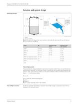
Function and system design Measuring principle BD: blocking distance, D: distance from sensor membrane to fluid surface, E: empty distance F: span (full distance), L: level, V: volume for mass), Q: flow Time-of-flight method The sensor transmits ultrasonic pulses in the direction of the product surface. There, they are reflected back and received by the sensor. The transmitter Prosonic S measures the time t between pulse transmission and reception. From t (and the velocity of sound c) it calculates the distance D from the reference point (see the figure —> S 4) to the product surface: From D...
Open the catalog to page 3
Prosonic S FDU90/91/91F/92/93/95/96 Blocking distance The level L may not extend into the blocking distance BD. Level echoes within the blocking distance can not be evaluated due to the transient characteristics of the sensor and thus a reliable measurement is not possible. The blocking distance BD is dependent on the type of sensor: FDU96 FDU90 FDU95 FDU93 1.6 (5.25) FDU95-#2###: 0.9 (3.0) FDU95-#1###: 0.7 (2.3) 0.6 (2.0) 0.4 (1.3) B 0.3 (1.0) C 0.07 (0.23) A FDU91 FDU92 m (ft) L00-FDU9xxxx-05-00-00-xx-002 A: Without flooding protection tube, B: With flooding protection tube, C: Reference point...
Open the catalog to page 4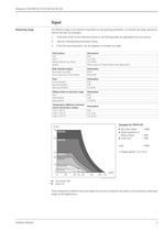
Measuring range The effective range of the sensors is dependent on the operating conditions. To estimate the range, proceed as follows (see also the example): 1. Determine which of the influences shown in the following table are appropriate for your process. 2. Add the corresponding attenuation values. 3. From the total attenuation, use the diagram to calculate the range. ■ Silo with rubble: ~ 40dB These measuring conditions have been taken into account during the calculation of the maximum measuring range in solid applications.
Open the catalog to page 5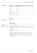
Operating frequency Signal transmission analogue voltages Power supply Power supply The FDU90 and FDU91 sensors are optional available in a version with heater. The power for this heater must be provided by an external power supply unit. The supply voltage is connected to the brown (BN) and blue (BU) strands of the sensor cable. Technical data ■ If the sensor heater is applied, the integrated temperature sensor can not be used. Instead, an external temperature sensor (PtlOO or FMT131 from Endress+Hauser) must be used. The transmitter FMU90 is available in a version with an input for the external...
Open the catalog to page 6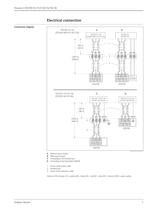
Electrical connection Connection diagram A Without sensor heater B With sensor heater 1 Screen of the sensor cable 3 Screen of the extension cable Colours of the strands: YE = yellow; BK = black; RD = red; BU = blue; BN = brown; GNYE = green-yellow
Open the catalog to page 7
Prosonic S FDU90/91/91F/92/93/95/96 Connection hints Caution! • In order to avoid interference signals, the sensor cables should not be laid parallel to high voltage electric power lines. The cables may not be laid in the proximity to frequency converters. • The cable screen serves as a return cable and must be connected to the transmitter without any electrical break. With the pre-assembled cables, the screen ends in a black strand (BK). With the extension cable, the screen must be twisted together and connected to the "BK" terminal. The cable screen must not be connected to the local potential...
Open the catalog to page 8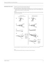
Prosonic S FDU90/91/91F/92/93/95/96 Shortening the sensor cable If required, the sensor cable can be shortened. Please note: • Do not damage the cores when removing the insulation. • The cable is shielded by a metallic braiding. This shielding serves as a return cable and corresponds to the black (BK) strand of the unshortened cable. After shortening the cable, loosen the metallic braiding, twist it together securely and connect it to the "BK" terminal. Caution! The protective earth conductor (GNYE), which is present in some of the sensor cables, may not be electrically connected to the cable...
Open the catalog to page 9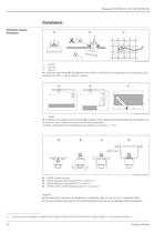
Installation options A: at girder or angle bracket, B: with alignment unit FAU40, in ATEXZone 20 the alignment unit can be used for zone separation, C: with a 1" sleeve welded to a grating A: Installation with cantilever and wall bracket, B: Installation with cantilever and mounting frame, C: The cantilever can be turned in order to position the sensor over the centre of the flume. Cantilever, wall bracket and mounting frame are available as accessories (-> 1 31). B: FDU90: Mounted at front thread (G Vh" orNPT Vh") C: FDUQx Mounted at rear thread (G 1" or NPT1") D: FDU90, FDU91, FDU92: Mounting...
Open the catalog to page 10All Endress+Hauser AG catalogs and technical brochures
 FTL41
FTL413 Pages
 FTL51B
6 Pages
 FMG50
FMG5010 Pages
 PTP31B
3 Pages
 Proline Promass E 300
13 Pages
 CUS71D
3 Pages
 iTEMP TMT162
3 Pages
 CLS54D
3 Pages
 CLS50D
3 Pages
 FMX21
FMX215 Pages
 Liquipoint FTW23
3 Pages
 Deltapilot FMB50
7 Pages
 iTHERM TM401
3 Pages
 COS61D
3 Pages
 Proline Promag 10W
4 Pages
 Proline Promag 10P
4 Pages
 Liquiphant FTL51
6 Pages
 FMD72
FMD725 Pages
 PMP51
PMP517 Pages
 Cerabar PMC51
7 Pages
 Cerabar PMP75
8 Pages
 Proline t-mass B 150
4 Pages
 Proline Prosonic Flow 93P
5 Pages
 Proline Prosonic Flow 92F
4 Pages
 FMD78
FMD788 Pages
 PMD75
PMD7510 Pages
 FMI51
FMI514 Pages
 FMU30
FMU307 Pages
 FMP57
FMP574 Pages
 FMP55
FMP554 Pages
 FMP54
FMP545 Pages
 FMP51
FMP515 Pages
 FMP50
FMP504 Pages
 FMR52
FMR524 Pages
 FMR51
FMR515 Pages
 F 200
F 20013 Pages
 D 200
D 20012 Pages
 E 100
E 1005 Pages
 C 200
C 20011 Pages
 Tophit CPS471 and CPS471D
20 Pages
 Tophit CPS491 and CPS491D
20 Pages
 B_unit4_1
1 Page
 B_unit3_3
1 Page
 B_unit3_2
1 Page
 Wort cooler
1 Page
 Condumax CLS16 and CLS16D
14 Pages
 Condumax CLS16D/CLS16
16 Pages
 Competence in Oil and Gas
30 Pages
 Pressure Transducer CT40
24 Pages
 Liquiphant T FTL20
20 Pages
 Deltabar S PMD70
96 Pages
 Gammapilot M FMG60
48 Pages
 Liquicap T FMI21
40 Pages
 Deltapilot S FMB70
56 Pages
 Micropilot FMR50
76 Pages
 Levelflex M FMP40
72 Pages


Archived catalogs
 Flow Measurement
32 Pages
 System components
20 Pages


- Endress+Hauser flow meter
- Endress+Hauser volume flow meter
- Endress+Hauser liquid flow meter
- Gas analyzer
- Concentration analyzer
- Monitoring analyzer
- Surge protector
- Resistance temperature sensor
- Pressure transmitter
- Liquids analyzer
- Level limit switch
- Endress+Hauser automatic analyzer
- Endress+Hauser waterproof flow meter
- Analog pressure transmitter
- Liquid level detector
- Endress+Hauser gas flow meter
- Endress+Hauser level sensor
- Benchtop analyser
- Endress+Hauser liquid level sensor