- Catalogs
- Endress+Hauser AG
- Micropilot FMR50
Micropilot FMR50
1 /76Pages

Micropilot FMR50
1 /76Pages
Catalog excerpts

Level Pressure Flow Temperature Liquid Registration Systems Services Solutions Analysis Components Technical Information Level radar Level measurement in liquids Continuous, non-contact level measurement of liquids, ■ Attractively-priced device for basic supply and storage applications as well as utility processes ■ Encapsulated PVDF or PP cladded horn antenna ■ Maximum measuring range: 30 m (98 ft); for version with enhanced dynamics: 40 m (131 ft) ■ Process connection : 1V2" thread , mounting bracket or with slip-on flange Your benefits ■ Reliable measurement even for changing product and process conditions ■ Integrated data memory (HistoROM) for high ■ Intuitive operating menu in national languages for easy commissioning ■ Simple integration into control or asset management ■ Exact diagnostic and process information to assist fast ■ International approvals for use in hazardous areas homogeneous or heterogeneous redundancy ■ System integration via HART/PROFIBUS PA (Profile People for Process Automation
Open the catalog to page 1
Table of contents Micropilot FMR50 Table of contents Important document information . . . . . . . . . . . . . . . . 3 Electromagnetic compatibility (EMC) . . . . . . . . . . . . . . . . . 48 Document conventions . . . . . . . . . . . . . . . . . . . . . . . . . . . 3 Function and system design . . . . . . . . . . . . . . . . . . . . 5 Measuring principle . . . . . . . . . . . . . . . . . . . . . . . . . . . . . 5 Input . . . . . . . . . . . . . . . . . . . . . . . . . . . . . . . . . . . . . 7 Process . . . . . . . . . . . . . . . . . . . . . . . . . . . . . . . . . . 49 Process temperature range...
Open the catalog to page 2
Important document information Document conventions Safety symbols Electrical symbols Symbols for certain types of information
Open the catalog to page 3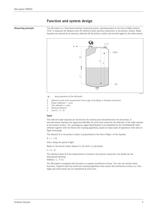
Micropilot FMR50 Function and system design Measuring principle The Micropilot is a "downward-looking" measuring system, operating based on the time-of-flight method (ToF). It measures the distance from the reference point (process connection) to the product surface. Radar impulses are emitted by an antenna, reflected off the product surface and received again by the radar system. R 100% D E F L 0% A0017870 Setup parameters of the Micropilot å1 R E F D L Reference point of the measurement (lower edge of the flange or threaded connection) Empty calibration ( = zero) Full calibration (= span) Measured...
Open the catalog to page 5
Micropilot FMR50 Output The Micropilot is commissioned by entering an empty distance "E" (=zero), a full distance "F" (=span) and application parameters. The application parameters are automatically adapt into the instrument to the process conditions. For models with a current output, the factory adjustment for zero point "E" and span "F" is 4 mA and 20 mA. For digital outputs and the display module, the factory adjustment for zero point "E" and span "F" is 0 % and 100 %. A linearization with max. 32 points, based on a table entered either manually or semi-automatically, can be activated locally...
Open the catalog to page 6
Measured variable The measured variable is the distance between the reference point and the product surface. Subject to the empty distance entered "E" the level is calculated. Alternatively, the level can be converted into other variables (volume, mass) by means of linearization (32 Measuring range Maximum measuring range Usable measuring range The usable measuring range depends on the size of the antenna, the reflectivity of the medium, the mounting location and eventual interference reflections. The following tables describe the groups of media as well as the achievable measuring range as a...
Open the catalog to page 7
Process tank with agitator Stilling well Turbulent surface. Single stage agitator (fI0t < 1 Hz) Antenna size Antenna size
Open the catalog to page 9
Operating frequency K-band (~ 26 GHz) Up to 8 Micropilot transmitters can be installed in the same tank because the transmitter pulses are statistically coded. Transmitting power 1) Product structure, feature 540: "Application package", option EM: "Advanced dynamics"
Open the catalog to page 10
Output signal HART FOUNDATION Fieldbus (in preparation) Switch output I I For HART devices, the switch output is available as an option. See product structure, feature 20: "Power Supply, Output", option B: "2-wire; 4-20mA HART, switch output" Devices with PROFIBUS PA and FOUNDATION Fieldbus always have a switch output.
Open the catalog to page 11
Signal on alarm Depending on the interface, failure information is displayed as follows: ■ Current output (for HART devices) - Failsafe mode selectable (in accordance with NAMUR Recommendation NE 43): Maximum alarm (= factory setting): 22 mA - Failsafe mode with user-selectable value: 3.59 to 22.5 mA - Status signal (in accordance with NAMUR Recommendation NE 107) - Plain text display ■ Operating tool via digital communication (HART, PROFIBUS PA, FOUNDATION Fieldbus) or service - Status signal (in accordance with NAMUR Recommendation NE 107) - Plain text display Linearization The linearization...
Open the catalog to page 12
FOUNDATION Fieldbus (in preparation)
Open the catalog to page 13
Transducer Blocks 1) depending on the configuration of the block Function Blocks
Open the catalog to page 14
EX Up to 20 blocks can be instantiated in the device altogether, including the blocks already instantiated
Open the catalog to page 15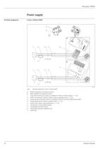
Micropilot FMR50 Power supply Terminal assignment 2-wire: 4-20mA HART 9 8 2- w 4-2 ire le 0 v 0m ope A n + 2 4 5 1 6 - 2 10 1 Sp a 711 re pa 08x rt xx mm A 4... HA 20mA RT el 4-2 HA mA [21 RT ] + + – – 4...20 mA 3 B 7 1 2 4 1-c 5 han [16 ] nel ove + 1 4-2 2 rvo 0m A ltag ep rote ctio n + + – – 711 286 17 4...20 mA 3 A0011294 å3 A B 1 2 3 4 5 6 7 8 9 16 Terminal assignment 2-wire; 4-20mA HART Without integrated overvoltage protection With integrated overvoltage protection Active barrier with power supply (e.g. RN221N): Observe terminal voltage (® ä 24) HART communication resistor (³250 W): Observe...
Open the catalog to page 16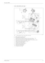
Micropilot FMR50 2-wire: 4-20mA HART, switch output 10 9 8 2- w 4-2 ire 0 HA mA [02 RT /03 ] PF S ope 7 + 1 2 6 10 4- + + – ³250W 2 3 1 Sp a 711 re pa 08x rt xx mm + + 3 -1 4 2 3+ n 4... HA 20 mA RT A 4...20 mA 4 5 B 3+ + 3 4-2 4 11 0m 2-c han 4[17 nel ] A/ ove rvo + 1 4-2 2 FIE 0mA LD / BU ep S ro ltag tec t + 711 286 19 – ³250W 1 ion + 2 3 4...20 mA 4 5 A0013759 å4 A B 1 2 3 4 5 6 7 8 9 10 11 Endress+Hauser Terminal assignment 2-wire; 4-20mA HART, switch output Without integrated overvoltage protection With integrated overvoltage protection Active barrier with power supply (e.g. RN221N): Observe...
Open the catalog to page 17All Endress+Hauser AG catalogs and technical brochures
 FTL41
FTL413 Pages
 FTL51B
6 Pages
 FMG50
FMG5010 Pages
 PTP31B
3 Pages
 Proline Promass E 300
13 Pages
 CUS71D
3 Pages
 iTEMP TMT162
3 Pages
 CLS54D
3 Pages
 CLS50D
3 Pages
 FMX21
FMX215 Pages
 Liquipoint FTW23
3 Pages
 Deltapilot FMB50
7 Pages
 iTHERM TM401
3 Pages
 COS61D
3 Pages
 Proline Promag 10W
4 Pages
 Proline Promag 10P
4 Pages
 Liquiphant FTL51
6 Pages
 FMD72
FMD725 Pages
 PMP51
PMP517 Pages
 Cerabar PMC51
7 Pages
 Cerabar PMP75
8 Pages
 Proline t-mass B 150
4 Pages
 Proline Prosonic Flow 93P
5 Pages
 Proline Prosonic Flow 92F
4 Pages
 FMD78
FMD788 Pages
 PMD75
PMD7510 Pages
 FMI51
FMI514 Pages
 FMU30
FMU307 Pages
 FMP57
FMP574 Pages
 FMP55
FMP554 Pages
 FMP54
FMP545 Pages
 FMP51
FMP515 Pages
 FMP50
FMP504 Pages
 FMR52
FMR524 Pages
 FMR51
FMR515 Pages
 F 200
F 20013 Pages
 D 200
D 20012 Pages
 E 100
E 1005 Pages
 C 200
C 20011 Pages
 Tophit CPS471 and CPS471D
20 Pages
 Tophit CPS491 and CPS491D
20 Pages
 B_unit4_1
1 Page
 B_unit3_3
1 Page
 B_unit3_2
1 Page
 Wort cooler
1 Page
 Condumax CLS16 and CLS16D
14 Pages
 Condumax CLS16D/CLS16
16 Pages
 Competence in Oil and Gas
30 Pages
 Pressure Transducer CT40
24 Pages
 Liquiphant T FTL20
20 Pages
 Deltabar S PMD70
96 Pages
 Gammapilot M FMG60
48 Pages
 Liquicap T FMI21
40 Pages
 Deltapilot S FMB70
56 Pages
 Prosonic S FDU91
40 Pages
 Levelflex M FMP40
72 Pages


Archived catalogs
 Flow Measurement
32 Pages
 System components
20 Pages


- Endress+Hauser flow meter
- Temperature probe
- Endress+Hauser volume flow meter
- Endress+Hauser liquid flow meter
- Gas analyzer
- Concentration analyzer
- Monitoring analyzer
- Surge protector
- Resistance temperature sensor
- Pressure transmitter
- Liquids analyzer
- Level limit switch
- Endress+Hauser automatic analyzer
- Analog pressure transmitter
- Endress+Hauser waterproof flow meter
- Liquid level detector
- Endress+Hauser gas flow meter
- Endress+Hauser level sensor
- Benchtop analyser
- Endress+Hauser stainless steel flow meter