
- Catalogs
- END-Armaturen GmbH & Co. KG
- Data sheet MA

Data sheet MA

Data sheet MA
The document outlines a diaphragm safety valve made of brass, designed to prevent pressure exceedance in systems. It operates automatically when pressure surpasses the set blow-out pressure and includes a manual override. Tested according to TRD 721 standards, it is suitable for heating systems (3 bar) and warm water systems (4, 6, 8, or 10 bar), with a maximum temperature of 120°C. The valve features a female thread connection per DIN 2999 standards.
The valve body is brass, the cap is ABS, and the diaphragm is EPDM.
Emphasizes safety during installation, maintenance, and repair, which should only be performed by trained personnel. Ensure the system is not under pressure during maintenance and follow all safety regulations to prevent accidents.
The valve should be installed vertically at the highest point of the heat generator or nearby. The blow-off line must match the valve's outlet size, have no more than two bends, and be no longer than 2 meters. It should be visible and positioned to avoid endangering people during operation.
The valve secures closed heating systems and warm water systems against pressure exceedance and is not classified as machinery under the 2006/42/EC directive.
Valves are high-quality products manufactured to recognized industrial standards. Installers and users must follow instructions precisely to maintain safety. Use within specified limits and intended purposes only. Never remove components under pressure, and ensure no damage before mounting or adjusting. After maintenance, check functionality and pipe connection tightness.
Diaphragm Safety Valves with code letter "H": Protect closed circuit heating systems with expansion tanks and water temperatures up to 120°C against overpressure, according to DIN 4751 part 2.
Diaphragm Safety Valves with code letter "W": Protect pressurized fluid systems in unvented water heaters against overpressurization, according to DIN4743 and AD-Merkblatt A3.
Diaphragm Safety Valves with code letter "H": Set at 3 bar by the manufacturer. A safety cap prevents unauthorized pressure changes.
Diaphragm Safety Valves with code letter "W": Set at 4, 6, 8, or 10 bar by the manufacturer. A safety cap prevents unauthorized pressure changes.
Diaphragm Safety Valves with code letter "H": Install vertically at the highest point of the heating system with the intake connection facing downwards. The discharge pipe should match the outlet's cross-section, have no more than 2 elbows, and be no longer than 2 meters. Ensure the outlet is unobstructed and safe.
Diaphragm Safety Valves with code letter "W": Install in the cold water inlet of the water heater at the highest point, following the arrow direction and DIN 1988. The connecting pipe must not be shut off, and no strainers or constrictions should be installed. The discharge pipe should match the outlet's cross-section, have no more than 2 elbows, and be no longer than 2 meters. Ensure the outlet is unobstructed and safe.
Catalog excerpts

Technische Daten BAUFORM Membran-Sicherheitsventil in Eckform mit Federbelastung. Zur Absicherung von unter Druck stehenden Systemen gegen Drucküberschreitung. Bauteilgeprüft nach TRD 721. DESIGN Diaphragm-pressure relief valve with oversized outlet, angle type, spring-loaded. Tested according TRD 721. BETÄTIGUNG Automatisches Öffen bei Überschreitung des eingestellten Abblasedruckes. Die Membrane ist anlüftbar. OPERATION Opens automatically, when the pressure exceeds the adjusted blow-out-pressure. Manual override is possible. ANSCHLUSS Innengewinde nach DIN 2999 Rp1/2 bis Rp11/4 CONNECTION Female thread acc. to DIN 2999 Rp1/2 bis Rp11/4 ANSPRECHDRUCK - Kennbuchstabe "H" für Heizungsanlagen nach EN12828 3 bar - Kennbuchstabe „W“ für Warmwasserbereitungsanlagen nach DIN 4753 Teil 1 4, 6, 8 oder 10 bar ACTION PRESSURE - code letter „H“ for heating systems acc. to EN 12828 3 bar • code letter „W“ for warm water heating system acc. to DIN 4753 Part 1 4, 6, 8 or 10 bar WERKSTOFFE Gehäuse: Kappe: Membrane: MATERIALS Body: Cap: Diaphragm: Alle Angaben sind freibleibend und unverbindlich! The above information is intended for guidance only and the company reserves the right to change any data herein without prior notice! Type: MA Safety valve 3 - 10 bar Dok.-Nr.: KAT-MA-1/6 07.11.2012 - Änderung: Abmessungen geändert Große / Size ["] Behälter-Inhalt / tank volume [l] Art. MA - Seite 1/6 END-Armaturen GmbH & Co. KG Postfach (PLZ 32503) 100 341 · Oberbecksener Str. 78 · D-32547 Bad Oeynhausen · Telefon (05731) 7900-0 · Telefax (05731) 7900-199 · http://www.end.de
Open the catalog to page 1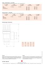
Artikel- u. Bestellangaben: z.B. MA126025 = Membran-Sicherheitsventil, Messing, Ansprechdruck = 6 bar, Innengewinde Rp 1" 1. + 2. Stelle Produkt MA = MembranSicherheitsventil 3. Stelle Gehäusewerkstoffe 1 = Messing Ordering example: e.G. MA126025 = Diaphragm-Safety valve, Brass, Action pressure = 6 bar, Female thread Rp 1" 1. + 2. Digit Product MA = DiaphragmSafety valve 3. Digit Body material 1 = Brass 6. Digit Action pressure Abmessungen / Dimension Hinweis Bei den in dieser Dokumentation beschrieben Produkten, in der von uns gelieferten Form, handelt es sich weder um Maschinen gemäß Artikel...
Open the catalog to page 2
In Abhängigkeit der technischen Gegebenheiten und des Zeitpunktes, unter denen bzw. zu dem Sie die Armaturen oder Ventile montieren, einstellen und in Betrieb nehmen, müssen Sie jeweils besondere Sicherheitsaspekte berücksichtigen! Wenn z. B. die Armaturen/Ventile in einer betriebsbereiten chemischen Anlage eingebaut sind, liegen die Gefahrenmomente der Inbetriebnahme in einer anderen Dimension, als wenn diese nur zu Testzwecken an einem „trockenen“ Anlagenteil in der Montagehalle erfolgt! Da wir die Umstände zum Zeitpunkt der Montage/Einstellung/Inbetriebnahme nicht kennen, nden Sie in den nachfolgenden...
Open the catalog to page 3
Prüfen Sie nach Abschluss der Wartung bzw. der Reparatur die korrekte Funktion der Armaturen/Ventile und Dichtigkeit der Leitungsverbindungen. 1.3 Die Armaturen/Ventile • sind nach den anerkannten Regeln der Technik hergestellte Qualitätsprodukte. • haben das Herstellerwerk in sicherheitstechnisch einwandfreiem Zustand verlassen! Um diesen Zustand zu erhalten, müssen Sie als Monteur/Anwender Ihre Aufgabe entsprechend den Beschreibungen in dieser Anleitung fachlich richtig und mit größter Präzision durchführen. Wir setzen voraus, dass Sie als ausgebildete Fachkraft über fundierte mechanische und...
Open the catalog to page 4
Operation and Installation Manual 1 Safety advice Depending on the technical circumstances and the time under and at which the armatures and valves are mounted, adjusted and commissioned, you must take into account particular safety aspects in each case! If, for example, a pressure relief valve works a slide in an operational chemical plant, the potential hazards of commissioning have another dimension from that when this is only being carried out for test purposes an a „dry“ part of the plant in the assembly room! Since we do not know the circumstances at the time of the mounting/adjustment/commissioning,...
Open the catalog to page 5
Device safety The armatures/valves • are quality products which are produced in accordance to the recognized industrial regulations. • left the manufacturer`s work in a perfect safety condition. In order to maintain this condition, as installer / user you must carry out your task in accordance with the description in these instructions, technically correctly and with the greatest possible precision . We assume, as a trained specialist you are having mechanical and electrical knowledge! Satisfy yourself that the armatures/vales will only be used within their admissible limiting value (see the...
Open the catalog to page 6All END-Armaturen GmbH & Co. KG catalogs and technical brochures
 Data sheet BO-BO
3 Pages
 Data sheet BH
2 Pages
 Data sheet BG
4 Pages
 Data sheet BF
2 Pages
 Data sheet BE
2 Pages
 Data sheet BC
2 Pages
 Data sheet AX
1 Page
 Data sheet AW
1 Page
 Data sheet AV
2 Pages
 Data sheet AS
4 Pages
 Data sheet AR
3 Pages
 Data sheet AM
2 Pages
 Data sheet AL
3 Pages
 Data sheet AG
3 Pages
 Data sheet AE
9 Pages
 Data sheet AD
3 Pages
 Data sheet AC
3 Pages
 Data sheet AB
3 Pages
 Data sheet AA
3 Pages
 Data sheet A
15 Pages
 Data sheet VH-ED
3 Pages
 Data sheet UV
10 Pages
 Data sheet TE
3 Pages
 Data sheet SV1
15 Pages
 Data sheet SG
4 Pages
 Data sheet SD24
4 Pages
 Data sheet SD
3 Pages
 Data sheet SD
4 Pages
 Data sheet RK
5 Pages
 Data sheet PD-EE
3 Pages
 Datenblatt PD-ED
3 Pages
 Data sheet NE
13 Pages
 Data sheet NBK
6 Pages
 Data sheet MEAG3S
3 Pages
 Data sheet KA
3 Pages
 Data sheet ED/EE
4 Pages
 Manual BV
28 Pages
 BV series
2 Pages
 Data sheet CB
3 Pages

Archived catalogs
 BC series
2 Pages
 KFE series
2 Pages
 IK series
4 Pages
 Strainer
4 Pages
 Relief Valves
2 Pages
 Non Return Valves
3 Pages
 Globe valve
2 Pages
 Solenoid Valves
4 Pages
 Pressure Actuated Valves
20 Pages
 Pneumatic Actuators
8 Pages
 Wafer-Type Ball Valve
5 Pages
 Knife Gate Valves
8 Pages

- Manual valve
- Control valve
- Stainless valve
- Water valve
- Ball valve
- Pneumatic valve
- Electrically operated valve
- Regulating valve
- Flange valve
- Liquid filter
- On/off valve
- Flap valve
- Check valve
- Lever valve
- Gas solenoid valve
- 2-way solenoid valve
- NC solenoid valve
- Direct-operated solenoid valve
- Pneumatically-operated valve