
- Catalogs
- emtrion GmbH
- SBC-RZN1D-3 - Hardware Manual

SBC-RZN1D-3 - Hardware Manual

SBC-RZN1D-3 - Hardware Manual
The SBC-RZN1D module is an industrial communication controller utilizing the Renesas RZ/N1D processor. It features dual Cortex-A7 CPUs and a Cortex-M3 CPU, designed for industrial Ethernet communication. Key specifications include 512 MB DDR3 RAM, 16 MB NOR Flash, 4 GB eMMC, multiple Ethernet interfaces, CAN interfaces, and serial ports. The module operates within a temperature range of -25°C to 70°C, with an extended range option available.
The block diagram provides an overview of the SBC-RZN1D's architecture, showcasing processor cores, memory interfaces, Ethernet interfaces, and other peripheral connections.
- Processor: The RZ/N1D processor includes dual Cortex-A7 CPUs and a Cortex-M3 CPU, supporting various industrial communication protocols.
- DDR3 SDRAM: 4-Gbit DDR3 SDRAM clocked at 500 MHz.
- NOR-Flash: 16 MB QSPI NOR Flash used as a boot device.
- eMMC: 4 GB eMMC for OS and application data, connected via SDIO1 interface.
- Ethernet Interfaces: Two 1Gb and two 100Mb Ethernet interfaces with specific PHY configurations.
- Serial Ports: Three user-accessible serial ports, including RS485 and RS232 interfaces.
- CAN: Two CAN controllers supporting ISO11898-1 specification.
- RTC: Integrated RTC with battery backup option.
- TPM: TPM SE050C connected to I2C1 interface.
- EEPROMs: Two EEPROMs for configuration data storage.
- LEDs: Status and activity LEDs controlled by GPIO pins.
Details on external and internal connectors, including power supply, Ethernet, serial interfaces, and USB connections.
Specifications covering electrical, environmental, EMC, and mechanical aspects of the module.
Provides a visual representation of the PCB layout and dimensions.
Lists documents and resources for further information.
LEDs are activated when the corresponding GPIO pins are driven high, specifically IO137 and GPIO136 for PHY4 LED1 and PHY5 LED1 respectively.
The USB1 interface is designated for internal use as a USB Device for production purposes and is not accessible to customers.
The SPI5 interface is internally available at a 6-pin header for future use and is not typically accessible to customers.
The module's power consumption is a maximum of 0.2 A at +24V, with a tolerance of +/- 50%. The actual current consumption varies based on the software in operation.
- J6: Power Supply - Phoenix Contact MSTBA 2,5/2-G with a mating connector MSTB 2,5/2-ST.
- J1, J2: RJ45 TCP/IP Connectors - Type 1G BASE-T with specified pin signals for data transmission.
- J8, J9: RJ45 Fieldbus Connectors - Type 10/100 BASE-T with specified pin signals.
- J4: Serial Interfaces - Phoenix Contact MSTBA 2,5/17-G with various RS232, RS485, and CAN signals.
- J3: SPI - Header 1x6, 2.54 mm (not fitted).
- J5: Console - Header 1x6, 2.54 mm.
- J10: JTAG - Header 2x5, 1.27 mm with specified pin signals.
- J11: USB Device - Microlatch with specified pin signals.
- Electrical Specifications - Supply voltage is 24V with a tolerance of +/-50%, and current consumption is up to 0.2 A.
- Environmental Specifications - Operating temperature ranges from -25 to +85°C for open boards and -25 to +60°C when mounted in an enclosure. Storage temperature ranges from -40 to +125°C, with relative humidity from 0 to 95% non-condensing.
- EMC Compliance - Complies with EN 61000-6-3: 2007 and EN 61000-6-2: 2019 standards.
- Mechanical Specifications - The board weighs approximately 80 g, is made of Glasepoxi FR-4, UL-listed, 8 layers, and measures 111.6 mm x 84.5 mm x 15.0 mm.
The document includes a dimensional drawing of the PCB layout.
The document references the datasheet for the RZ/N1D, RZ/N1S, and RZ/N1L Groups, Rev. 1.1, dated May 29, 2020.
Catalog excerpts

SBC-RZN1D-3 - Hardware Manual Hardware Manual 9 / 29.09.2022 emtrion GmbH
Open the catalog to page 1
© Copyright 2022 emtrion GmbH All rights reserved. This documentation may not be photocopied or recorded on any electronic media without written approval. The information contained in this documentation is subject to change without prior notice. We assume no liability for erroneous information or its consequences. Trademarks used from other companies refer exclusively to the products of those companies. Changes First release In chapters 2 and 3.3 NOR Flash reduced to 16 MB In chapter 3.5 details of Ethernet interfaces added Mechanical characteristics in chapters 5 and 6 corrected Added mating...
Open the catalog to page 2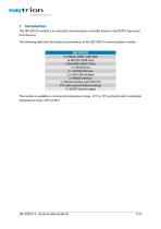
1 Introduction The SBC-RZN1D module is an industrial communication controller based on the RZ/N1D processor from Renesas. The following table lists the features and interfaces of the SBC-RZN1D communication module: SBC-RZN1D 512 MByte DDR3-1000 RAM 16 MB QSPI NOR Flash 4 GB eMMC NAND Flash 2 x Gb Ethernet 2 x 100 Mb Ethernet 2 x CAN 2.0B interface 2 x RS485 interface 1 x RS232 interface with RTS/CTS RTC with optional battery backup 12-36 VDC power supply The module is available in commercial temperature range -25°C to 70°C and optionally in extended temperature range -40°C to 85°C.
Open the catalog to page 4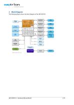
2 Block Diagram The following figure shows the block diagram of the SBC-RZN1D. JTAG JTAG Cache Cache 2 x ARM® Cortex®-A7 2 x ARM® Cortex®-A7 500 MHz 500 MHz with NEON and VFPv4 with NEON and VFPv4 Clocks Clocks INTC INTC Security Security QSPI QSPI with magnetics with magnetics SercosIII SercosIII Slave Slave NAND Flash NAND Flash I/F I/F EtherCAT EtherCAT Slave Slave with magnetics with magnetics Timer Timer JTAG, JTAG, CoreSight CoreSight Advanced 5 Port Advanced 5 Port Ethernet Switch Ethernet Switch with magnetics with magnetics Boot ROM 2 **GMAC Boot ROM 2 GMAC 16 MB 16 MB QSPI NOR Flash...
Open the catalog to page 5
3 Functional Description 3.1 Processor The SBC-RZN1D module is based on the processor RZ/N1D from Renesas [1]. This is a heterogeneous multi core processor which incorporates a Dual Cortex®-A7 CPU at 500 MHz and an additional Cortex®-M3 CPU at 125 MHz. The Cortex®-M3 CPU is part of a R-IN Engine for industrial Ethernet communication which additionally includes an Advanced 5 Port Switch, an EtherCAT slave controller, a Sercos III slave controller a HWRTOS GMAC and two GMACs. Besides the Ethernet interfaces further interfaces are available like CAN 2.0B and UARTs that are used at SBC-RZN1D. Further...
Open the catalog to page 6
The PHY of interface RGMII4 is configured at address 4. Its output LED0 is connected to the input SWITCH_MII_LINK[4] of the processor. The interface is available at RJ45 socket J8. The PHY of interface RGMII5 is configured at address 5. Its output LED0 is connected to the input SWITCH_MII_LINK[5] of the processor. The interface is available at RJ45 socket J9. 3.5.3 1Gb Interfaces The two Gb interfaces are connected to the interfaces RGMII1 and RGMII2 of the processor and available at the bottom side. PHYs of type KSZ9031RNX are used. They are controlled by an MDIO interface which is comprised...
Open the catalog to page 7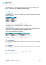
A second EEPROM AT24C16D is connected to I2C interface CAT_SCL/CAT_SDA at GPIO113 and GPIO112 of the processor. The 7-bit address of the EEPROM is 0x50. 3.11 LEDs 3.11.1 Status LEDs Two Dual-colour LEDs D1 and D2 are located at the front. The LEDs are driven by GPIO pins of the processor as following: LED D1-Green D1-Red D2-Red D2-Green The LEDs are on while the corresponding GPIO is driven high. The LEDs shine Yellow while both colours, Red and Green, are driven high,. 3.11.2 Activity LEDs The control of the green LEDs of the RJ45 sockets J8 and J9 at the front can be switched between the LED1...
Open the catalog to page 8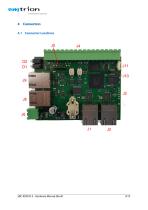
4 Connectors 4.1 Connector Locations
Open the catalog to page 9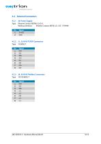
4.2 External Connectors 4.2.1 Type J6: Power Supply Phoenix Contact MSTBA 2,5/2-G Mating connector: Phoenix Contact: MSTB 2,5/ 2-ST, 1754449 Signal 24 VDC GND J1, J2: RJ45 TCP/IP Connectors 1G BASE-T Signal DA+ DADB+ DC+ DCDBDD+ DD- J8, J9: RJ45 Fieldbus Connectors 10/100 BASE-T Signal DA+ DADB+ n/c n/c DBn/c n/c
Open the catalog to page 10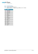
J4: Serial Interfaces Phoenix Contact MSTBA 2,5/17-G Mating connector: Phoenix Contact: MSTB 2,5/17-ST, 1754740 Signal RS232_RxD RS232_TxD RS232_CTS RS232_RTS GND RS485-1_B RS485-1_A GND RS485-2_B RS485-2_A GND CAN-1_H CAN-1_L GND CAN-2_H CAN-2_L GND
Open the catalog to page 11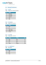
J5: Console Header 1x6, 2.54 mm Signal GND n/c n/c UART1_RxD UART1_TxD PU 10k J10, JTAG Header 2x5, 1.27 mm Signal 3.3V GND GND n/c TRST# J11: USB Device Microlatch Signal VBUS DM1 DP1 GND
Open the catalog to page 12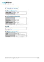
5 Technical Characteristics 5.1 Electrical Specifications Supply voltage Current consumption 5.2 Environmental Specifications Ambient temperature Open board Board mounted in enclosure Storage temperature Relative humidity 5.4 Mechanical Specifications Weight Glasepoxi FR-4, UL-listed, 8 layers
Open the catalog to page 13All Emtrion GmbH catalogs and technical brochures
 DIMM-MX6x
46 Pages
 DIMM-MX53x
40 Pages


- Communication gateway
- Industrial gateway
- Single-board computer
- Fieldbus gateway
- Ethernet gateway
- SoM
- IoT gateway
- USB 2.0 system-on-module
- USB 2.0 single-board computer
- Industrial single-board computer
- Linux system-on-module
- USB single-board computer
- HDMI single-board computer
- RS-485 single-board computer
- Linux single-board computer
- HDMI system-on-module
- RJ45 single-board computer
- Ethernet system-on-module
- Intel® Core™ computer-on-module
- RS232 single-board computer