- Catalogs
- emtrion GmbH
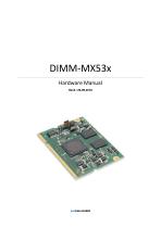
- DIMM-MX53x
DIMM-MX53x
1 /40Pages

DIMM-MX53x
1 /40Pages
Catalog excerpts
emtrion GmbH
Open the catalog to page 1
© Copyright 2012 emtrion GmbH All rights reserved. This documentation may not be photocopied or recorded on any electronic media without written approval. The information contained in this documentation is subject to change without prior notice. We assume no liability for erroneous information or its consequences. Trademarks used from other companies refer exclusively to the products of those companies. Date/Signature Changes 02.05.2011 First revision 31.05.2011 Added RGB table Added LVDS mapping tables Updated block diagram Changed processor clocks chapter 23.09.2011 Address bus extension possibility...
Open the catalog to page 2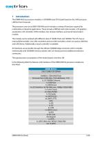
1 Introduction The DIMM-MX53x processor module is a SODIMM sized CPU board based on the i.MX processor i.MX53x from Freescale. The processor core runs at 800/1000 MHz and it includes a variety of functions required for multimedia or industrial applications. These include a MPEG4 and H.264 encoder, a 3D graphics accelerator, LCD controller, LVDS interface, two camera interfaces, and sound input/output module. The module can be ordered with different sizes of NAND-Flash and SDRAM. The CPU has an internal Ethernet MAC, two CAN controllers and two USB Controllers, which are used as USB Host and USB...
Open the catalog to page 5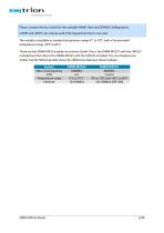
Please contact emtrion GmbH for the available NAND Flash and SDRAM Configurations. UART4 and UART5 can only be used if the Keypad function is not used. The module is available in standard temperature range 0°C to 70°C and in the extended temperature range -40°C to 85°C. There are two DIMM-MX53 modules at emtrion GmbH. One is the DIMM-MX537 with the i.MX537 included and the other is the DIMM-MX535 with the i.MX535 included. The most features are similar, but the following table shows the differences between these modules. feature Max. Core frequency CAN Temperature range Ethernet
Open the catalog to page 6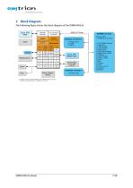
2 Block Diagram The following figure shows the block diagram of the DIMM-MX53x. Up to 1GB Up to 1GB RAM RAM SDRAM SDRAM Controller Controller Clock Clock ARM CortexA8 core ARM CortexA8 core 32-bit RISC processor 32-bit RISC processor with Vector with Vector Floating Point Unit Floating Point Unit DMA DMA Timer Timer Debug Debug JTAG JTAG Video Video Input Input Ext. Interface Ext. Interface Controller Controller Cache Cache Multimedia Multimedia Clock Interrupt Clock Interrupt Temp Temp Generator Controller Generator Controller System Chip System Chip RTC RTC Ctrl Security Ctrl Security Video...
Open the catalog to page 7
3 Handling Precautions Please read the following notes prior to installing the DIMM-MX53x processor module. They apply to all ESD (electrostatic discharge) sensitive components: The DIMM-MX53x does not need any configurations before installation. The module does not provide any on-board ESD protection circuitry – this must be provided by the product it is used in. Before installing the module it is recommended that you discharge yourself by touching a grounded object. Be sure all tools required for installation are electrostatic discharged as well. Before installing (or removing) the module,...
Open the catalog to page 8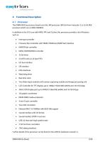
The DIMM-MX53x processor board uses the i.MX processor i.MX53x from Freescale [1], a 32-bit RISC processor which runs at 800/1000MHz. In addition to the CPU core with MMU, FPU and Caches, this processor provides a lot of features such as: Interrupt controller Processor Bus Controller with SRAM, PSRAM and NOR Flash interface NAND Flash controller 5 UARTs with 2x 32 byte FIFO IrDA interfaces Watchdog timer Real time clock Two Video input modules with camera capturing module and image processing unit 24bit LVDS display port up to WXGA (1366x768) @60Hz and 16/18/24 bpp NEON SIMD media accelerator...
Open the catalog to page 9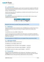
4.1.1 Processor Clocks The 24MHz main clock is generated by a quartz crystal. Four internal PLL multiply the 24MHz main clock to the internal clocks. All clocks in processor are derived from theses frequencies, via various software configurable dividers. The RCLK clock input of the CPU is supplied by a 32,768 kHz clock from the RTC chip and it is used for date and time applications. 4.1.2 Boot Mode The DIMM-MX53x can boot from the NAND-Flash or serial via USB or UART2. The boot mode is configured via the DIP Switch SW1. SW1-1 0 1 Boot source NAND-Flash Serial Booting from other devices is possible....
Open the catalog to page 10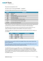
The processor bus signal level is 3,3V. The address space is in the range 0xF0000000 … 0xF00007FF. The following table describes the processor bus interface signals. signals A[10:0]* D[15:0] CKIO WAIT# CS# RD# WE0# WE1# RD/WR# description Address bus Data bus 66 MHz bus clock Low active wait input signal (must not be used) Low active chip select Low active read signal Low active low byte D[7:0] selection signal Low active high byte D[15:8] selection signal Low active write enable signal * These signals are used as boot configuration pins during reset. During reset these signals shall not be influenced...
Open the catalog to page 11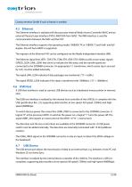
Contact emtrion GmbH if such a feature is needed. 4.5 Ethernet The Ethernet interface is realized with the processor internal Media Access Controller (MAC) and an external Physical Layer Interface (PHY) LAN8720A from SMSC. The RMII interface is used for communication between the MAC and the PHY. The Ethernet interface supports the operating modes 100BASE-TX or 10BASE-T, both half- and full duplex. Also HP Auto-MDIX is supported. The registers of the Ethernet PHY can be configured via the Media Independent Interface (MII). The Ethernet signal lines (ETH_TDP, ETH_TDM, ETH_RDP, ETH_RDM) as well...
Open the catalog to page 12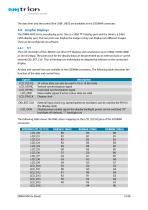
The data lines and the control line USBF_VBUS are available at the SODIMM connector. 4.8 Graphic Displays The DIMM-MX53x has two display ports. One is a 24bit TFT display port and the other is a 24bit LVDS display port. The two ports can display the image or they can display two different images. That can be configured via software. 4.8.1 TFT The LCD controller of the i.MX53x can drive TFT displays with resolutions up to 1080p (1920x1080) at 16/18/24bpp. The pixel clock for the display data can be generated by an internal clock or via the external DI0_EXT_CLK. Thus all timings can individually...
Open the catalog to page 13All Emtrion GmbH catalogs and technical brochures
 DIMM-MX6x
46 Pages
 SBC-RZN1D-3 - Hardware Manual
15 Pages


- Communication gateway
- Industrial gateway
- Single-board computer
- Fieldbus gateway
- Ethernet gateway
- Wireless gateway
- SoM
- IoT gateway
- USB 2.0 system-on-module
- USB 2.0 single-board computer
- Industrial single-board computer
- Linux system-on-module
- HDMI single-board computer
- USB single-board computer
- Embedded system-on-module
- Linux single-board computer
- RS-485 single-board computer
- HDMI system-on-module
- RS232 single-board computer
- RJ45 single-board computer