- Catalogs
- EMS Electro Mecanicals Systems
- DC SWITCH DCHS 32A
DC SWITCH DCHS 32A
1 /6Pages

DC SWITCH DCHS 32A
1 /6Pages
Catalog excerpts
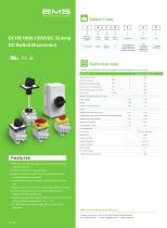
Electro Mechanical Systems Select Code DCHS 1000-1200VDC 32 Amp DC Switch Disconnect oTOus C € ^ EMC DC Disconnect Switch Rated Rated Number Current Voltage of Pole P=Panel Mounting B= Base Mounting D=Direct Command E=Mounting Enclosure Color R - Red Knob Yellow Plate B=Black knob Gray Plate Technical data Features Data according to IEC/EN60947-3:2009+A1+A2, AS60947.3, Utilization category DC-PV1, DC-PV2, DC-21B • Panel Mounting, Base Mounting, Direct Command or Mounting Enclosure optional. • Compact structure and modular design. • Parallel connections design, more big bore diameter makes connection fastness and flexibility. • Fast switching structure , arcing time normally occurs less than 3ms. • Self-cleaning contact mechanism, extending the lifespan of switch. • Dynamic sealing design and world class sealing materials guarantee an IP66 protection rate • UL94V-0 standard flame resistant materials , the product can be full loading operation at temperatures -40 C ~+70 C. • DC 1500V insulation voltage design, with TUV,CE,CB,SAA certification. EMS - Electro Mechanical Systems C/ Balango i Boter, 22, Atico (2a plt.) 08302, Mataro, Barcelona, Spain Tel: +34-625 14 3972 | Email: [email protected] | www.ems-sl.com
Open the catalog to page 1
Distribution Board - DC Switch Disconnect Dimensions Installation size of switch bottom Screw installation size Door Interlock – DC Switch Disconnect DCHS 32 BB/BRL 1-3mm Panel thickness Screw installation size Head panel installation size Length customizable Installation size of switch bottom guide
Open the catalog to page 2
Panel Mounting - DC Switch Disconnect Panel thickness Head panel installation size The three installation methods in the figure: A: 4 hole, center distance 48(no gasket) B: 4 hole, center distance 36(4 hole gasket) B: 2 hole, center distance 36(2 hole gasket) Screw installation size Installation size of switch bottom Panel thickness Head panel installation size The three installation methods in the figure: A: 4 hole, center distance 48(no gasket) B: 4 hole, center distance 36(4 hole gasket) B: 2 hole, center distance 36(2 hole gasket) Screw installation size Installation size of switch bottom
Open the catalog to page 3
Electro Mechanical Systems
Open the catalog to page 4
Electro Mechanical Systems Switching example YY YY Type
Open the catalog to page 5
EMS - Electro Mechanical Systems C/ Balançó i Boter, 22, Ático (2ª plt.) 08302, Mataró, Barcelona, Spain Tel: +34-625 14 3972 | Email: [email protected] | www.ems-sl.c
Open the catalog to page 6All EMS Electro Mecanicals Systems catalogs and technical brochures
 INOX PUSH BUTTONS 19mm
8 Pages
 DC SWITCH DCVS 40-55A
6 Pages
 DC SWITCH DCVS 16-32A
6 Pages
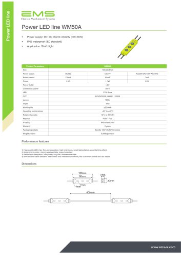 LED SHAFT LIGHT SYSTEM
2 Pages
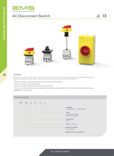 AC Disconnect Switch
12 Pages
 Company Profile
42 Pages
 Operators
31 Pages

- Single-pole switch
- Junction block
- Push-button switch
- Multipole switch
- Screw connection terminal block
- Limit switch
- Rotary electric switch
- Multipole disconnect switch
- Illuminated push-button switch
- Potentiometer
- Action push-button switch
- Electrical socket
- IP65 push-button switch
- Control station box
- Plastic switch
- Manual potentiometer
- Bipolar switch
- Hermetic switch
- Momentary push-button switch