- Catalogs
- EMKO Elektronik
- proop User Manual
proop User Manual
1 /193Pages

proop User Manual
1 /193Pages
Catalog excerpts

proop User Manual
Open the catalog to page 1
PROOP Builder User Manual. EN PROOP 02 V06_1019 1
Open the catalog to page 2
PROOP Builder
Open the catalog to page 3
PROOP Builder
Open the catalog to page 4
PROOP Builder
Open the catalog to page 5
PROOP Builder User Manual. EN PROOP 02 V06_1019 5
Open the catalog to page 6
PROOP Builder A) Operator Panel EMKO PROOP provides high speed vector based graphics with powerful Cortex A series CPU. Proop Builder software has user friendly design for rapid and easy development. A.1. Features A.1.1. Features Graph And Design • More than 100 ready to use vector-based elements. • Vector based image (SVG) support. • BMP, GIF, JPG, JPEG, PNG, PBM, PGM, PPM, TIFF, XBM, XPM image format support. • Improved graphics engine; Antialiasing, alphablending support A.1.2. Support Free type and Windows® Font Supports TrueType (TTF), PostScript Type1 (PFA/PFB), Bitmap Distribution Format...
Open the catalog to page 7
PROOP Builder A.1.5. Regional Formatting Format Support The time, date, and number formats are sensitive to regional settings. A.1.6. User Friendly EMKO Macro Emko Macro is designed to perform custom control functions and calculations with internal I/O and communication devices. Macro is described under the heading 'Macro'. A.1.7. Internal Analog/Digital IO Port Support The user can control the data with the macro and visual elements. A.1.8. Online/Offline Simulation Mode Compiled program is simulated in the PC environment without PROOP device. A.1.9. Industry Standard Multiple Communication...
Open the catalog to page 8
PROOP Builder A.2. PROOP Builder Setup Minimum system requirements for Proop Builder Software install: • 1GHz or greater CPU • 1GB RAM • 2GB Hard Disk (least 500 MB of free memory) • RJ45 Ethernet Network Cable • USB 1.1 Port Input • Windows XP, Windows Vista, Windows 7, Windows 8, Windows 8.1, Windows 10 operating systems. Please, follow the steps on the below for installation. Step 1: It is strongly recommended that before proceeding, you ensure that no other Windows programs are running. Step 2: Run the Proop Builder setup file "Proop Builder VX.X.X Setup.exe" to start the installation process....
Open the catalog to page 9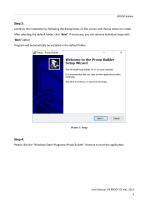
PROOP Builder Step 3: Continue the installation by following the dialog boxes on the screen and choose where to install. After selecting the default folder, click ‘Next’. If necessary, you can retrieve individual steps with ‘Back’ option. Program will automatically be installed in the default folder. Step 4: Please click the “Windows Start>Programs>Proop Builder” shortcut to start the application. User Manual. EN PROOP 02 V
Open the catalog to page 10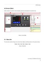
PROOP Builder B) Screen Editor Editor contains six sections; tool and sidebar, elements and property list, element tree. Picture 2: Screen Editor B.1. Menu Bar The menu bar contains Project, Form, Edit, Tools, Options and Help sections as the picture below. User Manual. EN PROOP 02 V06_1019 10
Open the catalog to page 11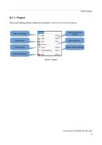
PROOP Builder B.1.1. Project Menu with editing options related to the project. There are sub menus as below. Open project from a folder Save project Close project Open project’s settings Quit Proop Builder Picture 4: Project User Manual. EN PROOP 02 V06_1019 11
Open the catalog to page 12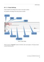
PROOP Builder B.1.1.1. Project Settings Project properties and settings that are active on this page are edited. The properties and settings of the active project are edited. New project Open project Save project Delete project Project’s path Model selection Project’s name Project owner’s name Picture 5: Project Settings When you click on “Properties” sections in the field 1, form screen appears. In the picture above contains field descriptions. User Manual. EN PROOP 02 V06_
Open the catalog to page 13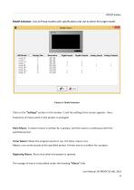
PROOP Builder Model Selection: Lists all Proop models with specifications and use to select the target model. Picture 6: Model Selection Click on the “Settings” section in the number 2 and the settings form screen appears. Here, frequency of macro work in the project is arranged. Main Macro: A master macro is written for a project, and this macro is continuous with the specified period. Timer Macro: When the program starts to run, the timer macro runs. Macro, runs continuously at the specified period. A timer macro is written for a project. Beginning Macro: Runs once when the project is opened....
Open the catalog to page 14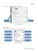
PROOP Builder The desired macro is selected and edited as shown below. Select desired macro Enter period B.1.2. Form A menu has with options for the form. There are sub menus as below. Add new form Delete current form Save current forum as template Open saved form template Save form as image Print form Preview form Open form preferences Picture 8: Menu Bar->Form User Manual. EN PROOP 02 V06_1019 14
Open the catalog to page 15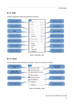
PROOP Builder B.1.3. Edit Contains regulations about the elements in the form. Undo last action Redo last action Copy selected Delete selected Send selected to back Bring selected to front Group options Widget options Size options Alignment options Distribute options Picture 9: Menu Bar->Edit B.1.4. Tools Contains general tools related to the project. There are sub menus as below. Download project to HMI Upload project from HMI Update HMI Proop Firmware Open Resource Editor Start Online Simulator Find & Replace Open Widget List Language selection Picture 10: Menu Bar->Tools User Manual. EN PROOP...
Open the catalog to page 16
PROOP Builder B.1.4.1. Uploads To upload the project files you can use USB Cable or USB disc. Project Upload Via Port • To upload the project to the device, plug the USB cable into the device. • Click to 'Tools Bar>Download' or press 'F5' on keyboard. • Click on the icon in the bottom left of the Proop Builder Program. Uploading Project with USB Memory • To upload the project into the device, create a folder named 'emko' or 'proop' in your USB memory Example upload folder: “G:\proop”, “G:\emko” • Copy the project file (*.emkp) into the upload folder. • If your project contains resource files...
Open the catalog to page 17
• The files that should be located in the folder named Proop are as follows . • Unplug the USB after copying to USB memory is finished. • Plug it into the USB port on the back of the device. • When you switch off the power and switch again, you can follow the project installation status via the device screen.
Open the catalog to page 18All EMKO Elektronik catalogs and technical brochures
 60W Power Supply Module
2 Pages
 EMKO OVEN CONTROLLER-SINGLE
2 Pages

