

S&L MONITOR

S&L MONITOR
- Power Supply: 12V to 30V DC
- Power Consumption: Max 2W
- Inputs: 18 digital inputs (GND or +24V)
- Indicators: 37 color-coded LEDs (red, blue, white, yellow)
- Electrical Connection: 8 pin + 13 pin connector
- Connector Cross Section: 0.5 to 1.5 mm² (AWG 28-16)
- Enclosure Protection: IP 65 front panel (IEC 529)
- Operating Temperature: -25°C to +85°C
- Dimensions: 144x48x68 mm (IEC 61554)
- Weight: 0.2 kg
- SLM 7S: 7 shutters
- WL: Integrated water tank level indicator
- WL - FL: Integrated water and foam tank level indicator
Catalog excerpts
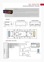
DIMENSIONS AND WIRING DIAGRAM / INSTALLATION The S&L Monitor is designed to monitor open side boxes (shutters), roof boxes, ladder and display the status of different kind of emergency and other lights on the special vehicle. Key advantage: Water and foam remote display can be integrated in the panel. The state of monitored devices will be displayed as color- coded LED warning lights. Monitoring is provided throught18 digital inputs. Digital inputs are connected via uP to 37 LED lights.Digital inputs can be connected to GND or +24V signal, to detect the status of connected lamps, shutters or other switches. An integrated photo sensor detects the ambient light and automatically adjusts the LED intensity for day or night operation. REAR PANEL CONNECTORS WIRING DIAGRAM / INSTALLATION O—I Power supply line, +12 to30 V DC •3—IT: 1 wire tank level gauge conection~|- MASTER CONTROL UNIT - MCU MASTER TANK LEVEL GAUGE
Open the catalog to page 1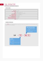
SPECIFICATIONS AND ORDERING INFORMATION SPECIFICATIONS Power supply Power consumption* Inputs Indicators Electrical Connection Connector cross section Enclosure - protection ( IEC 529) Operating temperature Dimensions of the indicator (IEC 61554) Automatically adjustable LED intensity Weight 12V ... 30V DC max. 2W 18 digital inputs, GND or +24V 37 color-coded LED (red, blue, white, yellow) 8 pin + 13 pin connector 0,5 to 1,5 mm2 (AWG 28-16) IP 65 front panel -25°C...+85°C 144x48x68 mm photo sensor 0,2 kg ORDERING INFORMATION Use the RED character from the chart below to construct a basic product...
Open the catalog to page 2All EMITTER catalogs and technical brochures
 PRESSURE SENSORS
1 Page
 FLASHER
1 Page
 MASTER CONTROL UNIT - MCU
3 Pages
 PUMP CONTROL UNIT - PCU
3 Pages
 TANK LEVEL GAUGES - TLG NTS
2 Pages
 TANK LEVEL GAUGES - TLG RTS
2 Pages
 TANK LEVEL GAUGES - TLG08
2 Pages
 Didital Pressure Indicator
2 Pages
 TANK LEVEL GAUGE TLG20D
2 Pages
 CONDUCTIVE LIQUIDS
2 Pages


Archived catalogs
 Didital Pressure Indicator
2 Pages
 Continiuous liqud level gauges
2 Pages
 PTO Timer
2 Pages
 Master Control Unit
2 Pages
 Pressure governors
2 Pages
