Catalog excerpts

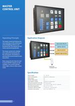
16 17 MASTER CONTROL UNIT Operating Principle The master control unit features the most used keys on the control panel of the fi refi ghting vehicle in one functional unit. The controls are very clearly represented graphically. The master control unit is divided into a grid of fi ve horizontal and fi ve vertical lines. The buttons or warning LEDs can be located at each intersection. Relay outputs for the inductive load or power MOSFET outputs are also available. It can control solenoid valves, lights, sirens or other custom needs. Application Diagram Power supply 10 ... 30 V DC Power consumption depends on confi guration Relay output Yes MOSFET GND output Yes Input Digital / analog depends on confi guration Enclosure protection ( IEC 529) IP65 (front panel) Dimension of the control unit 192 x 144 x 55 (288 x 144 x 55 - optional) Operating temperature from -25 °C to +65 °C Transducer cable for TLG08 2 x 0,50 mm2 + connector M12 Connector cross section 0.5-2.5 mm2 (AWG 24 - 12) Specifi cation
Open the catalog to page 1
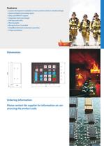
Features • Custom development available to meet customer needs or standard design • Optional digital and analog inputs • Relay and MOSFET outputs • Integrated Tank Level Gauge • Soft keys with LED’s • Warning lights • Microprocessor Controlled • Simplified electrical connections save time • Simple installation Dimensions Ordering information Please contact the supplier for information on con- structing the product code.
Open the catalog to page 2All EMITTER catalogs and technical brochures
-
PRESSURE SENSORS
1 Pages
-
FLASHER
1 Pages
-
S&L MONITOR
2 Pages
-
MASTER CONTROL UNIT - MCU
3 Pages
-
PUMP CONTROL UNIT - PCU
3 Pages
-
TANK LEVEL GAUGES - TLG NTS
2 Pages
-
TANK LEVEL GAUGES - TLG RTS
2 Pages
-
TANK LEVEL GAUGES - TLG08
2 Pages
-
Didital Pressure Indicator
2 Pages
-
TANK LEVEL GAUGE TLG20D
2 Pages
-
CONDUCTIVE LIQUIDS
2 Pages
Archived catalogs
-
Didital Pressure Indicator
2 Pages
-
Continiuous liqud level gauges
2 Pages
-
PTO Timer
2 Pages
-
Pressure governors
2 Pages


