- Catalogs
- Emerson Automation Solutions - TESCOM
- CROSBY H-SERIES DIRECT SPRING SAFETY VALVES

CROSBY H-SERIES DIRECT SPRING SAFETY VALVES

CROSBY H-SERIES DIRECT SPRING SAFETY VALVES
The document provides comprehensive technical specifications and features of the Crosby H-Series Direct Spring Safety Valves, focusing on the ISOFLEX® models. These valves are designed for overpressure protection in steam applications, adhering to ASME Boiler and Pressure Vessel Code Sections I and VIII.
- ASME/NB certified capacities for steam.
- Set and tested on steam with full nozzle flanged options.
- Long service life with low maintenance requirements.
- Two-ring set pressure and blowdown control.
- ISOFLEX seat tightness up to 93%.
The H-Series valves are suitable for steam safety applications such as economizers, steam drums, superheaters, and reheaters.
- Sizes range from 1¼” F 1½” to 6” RR 10”.
- Orifice sizes from 0.307 to 19.29 in².
- Temperature range up to 1120 °F (604 °C).
- Set pressures from 15 to 5000 psig.
The document includes a selection matrix for optimal valve placement in steam systems, with specific recommendations for different pressure ranges and applications such as drum, superheater outlet, reheater inlet, and economizer.
- Designed for high pressure, high capacity applications on boiler drums.
- Features include extended uptime, reduced maintenance costs, and minimized installation costs.
- Technical specifications include sizes from 2½” x 6" to 4" x 8", with maximum temperatures up to 750°F and set pressures up to 3060 psig.
- Suitable for 300 to 3000 psig steam generators.
- Features include increased operating efficiency, reduced maintenance costs, and minimized installation costs.
- Technical specifications include sizes from 1½” x 3" to 6" x 10", with maximum temperatures up to 1120°F and set pressures up to 3000 psig.
The document lists materials used for various valve components and recommends maintaining an inventory of spare parts for maintenance and repair.
The Crosby H-Series ISOFLEX® safety valves are engineered for reliability and efficiency in high-pressure steam applications, offering customizable features to meet specific operational needs.
The adjustable nozzle and guide rings utilize the reactive and expansive forces of flowing steam to provide full capacity lift. Valve capacity is determined solely by the nozzle throat area. High capacity valves ensure positive overpressure protection with fewer valves.
The ISOFLEX® disc insert is designed for pressure and temperature equalization, ensuring the seats remain flat during service.
Blowdown control is precise with two adjustable rings, allowing adjustments from 2 to 4% under operating conditions.
Close machining tolerances ensure precise centering of the disc insert, with special materials and finishes ensuring low friction guiding at all temperatures. The open bonnet minimizes thermal effects, ensuring valves open precisely at their set pressure.
The document lists various materials used for different parts of the valve, including carbon steel, stainless steel, Inconel®, and nickel alloy, with maximum temperature ratings provided for each material.
The document provides detailed specifications for the Crosby H-Series Style HCI ISOFLEX valves, including valve sizes, orifice areas, maximum set pressures, and temperature limits for different materials and configurations.
Dimensions and approximate weights for various valve sizes and styles are provided, including details for both welded and flanged configurations.
Additional notes include recommendations for maintaining spare parts inventory and using genuine Crosby parts to ensure product performance and warranty.
1. The 'W' is omitted from the style designation for standard welded inlets. For optional flanged inlet valves, the 'W' is dropped.
2. An additional dismantling height of 20 inches (508 mm) is required.
3. Weld preparation must adhere to customer specifications. Safety valves should be mounted on a nozzle with an inlet diameter equal to or greater than the nominal valve inlet size, dimension A. Refer to ASME boiler and pressure code Section I and ANSI/ASME B31.1 for recommended installation.
4. Bolt holes straddle the centerline on flanged connections. Drain specifications are ½” NPT for inlet sizes 1½” to 4” and ¾” NPT for 6” inlet size.
The document provides detailed specifications for various valve models (HCI-36, HCI-38, etc.) including inlet sizes, orifice areas, maximum set pressures, and temperatures for standard body materials. It also lists standard and optional flanged outlet classes, and dimensions in metric units for different valve styles.
1. For applications exceeding ASME/ANSI B16.34 pressure/temperature limits, specified HCI-( )W (welded only) valves are designed for maximum set pressure at maximum temperature stated in the table.
2. Set pressure is limited to either the inlet pressure limit per ASME/ANSI B16.34 or the maximum set pressure, whichever is lower.
3. Style HE ISOFLEX® safety valves are recommended for high-pressure drum saturated steam service between 138-207 barg.
The HCI-R ISOFLEX® style offers a restricted lift option available on all HCI ISOFLEX® valve sizes with either flanged or weld end connections. Capacities can be adjusted from 100% to 30% of full rated capacity, allowing for economic distribution of relieving capacity and reducing reaction forces.
1. Increases operating efficiency with a FLEXI-DISC seat design for pressure and temperature equalization, ensuring a flat and tight seal.
2. Reduces maintenance costs with a replaceable full nozzle design and single bonnet design for easy set pressure changes.
3. Minimizes installation costs with a high discharge coefficient for economical valve selection.
The Crosby H-Series Style HSJ safety valves are designed for use in high-pressure and high-temperature applications, such as boilers and Dowtherm® systems. They are available in sizes ranging from 1½” x 2” to 6” x 8” with orifice areas from 0.307 to 11.045 in². The valves support inlet ratings from ANSI Class 150 to 2500, with a maximum temperature of 1000°F (538°C) and a maximum set pressure of 2700 psig (186.2 barg). They comply with ASME I and VIII codes.
The HSJ valves are recommended for boiler pressures from 15-600 psig and are designed for economizer and Section VIII applications up to 2700 psig and 1000°F. They feature an adjustable nozzle ring and guide ring for full lift and high capacity, ensuring overpressure protection with minimal valves. The FLEXI-DISC® ensures a tight seal at 93% of the valve’s set pressure.
The two-ring design allows for precise blowdown control, adjustable while installed. The disc centering ensures precise opening at set pressure. Options include closed and open bonnets, with closed bonnets recommended for outdoor service under ASME Section VIII.
Specifically designed for Dowtherm® service, this variant features an unvented closed bonnet and alloy steel spring for high temperatures, meeting ASME Section I requirements for organic fluid vaporizer generators.
The valves are constructed from materials suitable for high temperatures, including carbon steel, alloy steel, stainless steel, and nickel alloy. Spare parts are categorized into consumable, repair, and insurance parts, with recommendations for maintaining an inventory of genuine Crosby parts.
The valves are available in various classes (150, 300, 600, 900, 1500, 2500) with different pressure and temperature limits. Detailed specifications include valve size, orifice area, maximum set pressure, and material options.
Installation and maintenance instructions are available upon request, emphasizing the importance of using genuine parts and following proper procedures for optimal performance.
The document outlines the specifications for the Model EFS drip pan elbow, which is designed to be used with safety valves. The sizes available range from 1½” to 8”, with a flange ANSI Class of 150. The material used is carbon steel, and it features a welding neck flange. The dimensions and specific requirements for installation are provided to ensure compatibility and safety.
The Crosby H-Series Style HCA-I-118W safety valves are highlighted for their ability to increase operating efficiency and reduce maintenance and installation costs. Key features include restricted lift options, seat tightness up to 93%, and two-ring control for adjusting overpressure and blowdown. These valves are suitable for ASME VIII off boiler steam applications and are designed to withstand supercritical pressure steam generator conditions.
The valves comply with several certifications and approvals, including the ASME Boiler and Pressure Vessel Code, National Board of Boiler and Pressure Vessel Inspectors Capacity Certifications, Pressure Equipment Directive (97/27/EC), and China Manufacturing License (TS).
The technical data section provides detailed information on inlet sizes, inlet and outlet ratings, maximum set pressures, temperature range, orifice sizes, and blowdown percentage. The valves are designed to handle maximum set pressures of 5,000 psig and temperatures up to 1100°F.
The document lists the materials used for various parts of the Style HCA-I-118W safety valves, including ASME SA217 Grade WC9 for the body, 316 stainless steel for the nozzle ring, and NI-CU Alloy for the disc holder. The materials are chosen for their durability and ability to withstand high temperatures.
Detailed dimensions and weights for different valve sizes are provided, including information on inlet and outlet sizes, orifice designations, and approximate weights. This information is crucial for ensuring proper installation and compatibility with existing systems.
The document includes tables showing the saturated steam capacities for various styles and set pressures, measured in pounds per hour at 3% overpressure. These capacities are certified by the National Board of Boiler and Pressure Vessel Inspectors and are essential for determining the appropriate valve size for specific applications.
- Saturated Steam Capacities: The document lists steam capacities in kilograms per hour at 3% overpressure for different set pressures ranging from 1.034 to 50 barg. The capacity is calculated using a formula that converts valve set pressure from barg to psig, then calculates in pounds per hour using the ASME Section I Capacity formula, and finally converts to kilograms per hour.
- Notes on Overpressure: For steam capacities at 10% overpressure, a specific ratio is provided to adjust the capacities listed in the tables. Additionally, for superheated steam, a correction factor (Ksh) is applied, which is detailed on pages 60-61 of the document.
- Set Pressures and Orifice Areas: The document provides a detailed table of set pressures in barg and corresponding orifice areas in square millimeters for different valve styles (F, G, H, J, K, L, M, N, P, Q).
- Superheat Correction Factor: A table is provided for the superheat correction factor (Ksh) based on flowing pressure and total temperature of superheated steam, ranging from 400°F to 1100°F.
- USCS Units Capacities: The document also includes steam capacities in pounds per hour for the US customary system, with specific orifice sizes (1.840 in² and 2.545 in²) and inlet pressures (P1) in psig. Capacities are certified by the National Board of Boiler and Pressure Vessel Inspectors and comply with the ASME Boiler and Pressure Vessel Code, Section I.
- Capacity Calculation: The capacity is calculated by converting the valve set pressure from barg to psig, using the ASME Section I formula, and converting to kilograms per hour.
- Overpressure Adjustments: For 10% overpressure, capacities are adjusted using a specific ratio involving the set pressure in psig.
- Superheat Correction: For superheated steam, capacities are adjusted using the superheat correction factor (Ksh) provided in the document.
- Certification: Capacities are certified by the National Board of Boiler and Pressure Vessel Inspectors and comply with ASME standards.
- Boilers with more than 500 sq. ft. of bare tube must have two or more safety valves, with specific capacity requirements for each valve.
- Superheater and reheater safety valve requirements are specified, including minimum relieving capacities and placement guidelines.
- Economizer safety relief valves must have a discharge capacity based on maximum expected heat absorption.
- Organic fluid vaporizer safety valves must be enclosed and discharge vapors safely, with specific calculations for minimum relieving capacity.
This document provides detailed pressure and temperature limits for various valve styles and materials, specifically focusing on the Crosby H-Series valves. The limits are categorized based on the body material and ANSI standard class, referencing ASME/ANSI B16.34 - 1996 standards.
- HSJ-( )6 Valves: Body material SA 216 Gr. WCB, with pressure/temperature limits specified for ANSI classes 150, 300, 600, 900, 1500, and 2500.
- HCI-( )6 Valves: Body material SA 216 Gr. WCC, with limits for ANSI classes 300, 600, 900, 1500, and 2500.
- HSJ-( )7 and HCI-( )8 Valves: Body material SA 216 Gr. WC6, with similar class specifications.
- HCI-( )9 Valves: Body materials SA 217 Gr. WC9 and SA 217 Gr. C12A, with detailed limits for ANSI classes 300 to 2500.
The document includes extensive tables showing working pressures (psig) across a range of temperatures (°F) for each valve style and material. These tables are crucial for determining the operational limits and ensuring safety and efficiency in valve applications.
The document also discusses outlet reaction forces for valve styles HE, HCI, and HSJ. It explains the calculation of total resultant forces at the outlet elbow when the valve is open and discharging. The forces are categorized into horizontal (Fh) and vertical (Fv) components, with equations provided for determining these forces based on flow, velocity, area, and static pressure.
- Vertical Force (Fv): Fv = (W * V + A * Pe) / gc, where W is flow, V is velocity, A is area, Pe is static pressure, and gc is the gravitational constant.
This document is essential for engineers and designers working with Crosby H-Series valves, providing necessary specifications to ensure compliance with safety standards and optimal performance under specified conditions.
Safety relief valves should be connected directly to the boiler, minimizing any intervening piping or fittings. The inlet piping must be robust enough to withstand discharge reactions. For piping systems, safety valves should be positioned downstream from pressure reducing valves, with nozzles designed to counterbalance discharge reactions. Multiple smaller valves are preferred over a single large valve, with staggered set pressures within ASME code limits.
The minimum differential pressure between valve set and operating pressure should be at least 5% to ensure seat tightness. Nozzles should match or exceed the valve nominal size, especially for off-center installations.
Discharge piping should be as direct as possible, with adequate sizing to prevent steam blowback. Flexible connections or expansion bends are recommended to accommodate thermal expansion without stressing the valve outlet.
Manifold lines should be sized to accommodate all discharge lines, with independent support and adequate drainage. Discharge lines should enter the manifold at an angle to minimize back pressure.
Hydrostatic test plugs are recommended for welded inlet valves, and testing should be completed before installing flanged inlet valves.
Drains should be provided for valve bodies and discharge systems to safely dispose of condensate and prevent personnel injury.
This software offers a comprehensive platform for sizing and selecting pressure relief devices, featuring an improved user interface, industry-standard methodologies, and integration with product literature. It supports various applications, including tank protection and blanketing.
Catalog excerpts

EMERSON. CROSBY H-SERIES DIRECT SPRING SAFETY VALVESDirect spring safety valves that provide comprehensive overpressure protection for ASME Boiler and Pressure Vessel Code Section I, and Section VIII steam safety applicationsFEATURES HCI ISOFLEX' • ASME/NB certified capacities for steam. • Set and tested on steam. • Full nozzle flanged option. • Restricted lift for customized capacity. • Long service life. • Low maintenance. • Two ring set pressure and blowdown control. • ISOFLEX seat tightness up to 93%. For seat tightness greater than 93% consult factory. TECHNICAL DATA GENERAL APPLICATION H-Series direct spring operated safety valves are the proven solution for comprehensive overpressure protection on steam safety applications including economizers, steam drums, superheaters, reheaters and more. Sizes: Orifices: Connections: Temperature range: Set pressures: IVi" F IV2" to 6" RR 10" 0.307 to 19.29 in2 (1.98 to 124.45 cm2) Flanged or welded inlet 1120 °F (604 °C) 15 to 5000 psig (1 to 345 barg) Code: ASME Boiler and Pressure Vessel Code Section I, and Section VIII Emerson.com/FinalControl © 2017 Emerson. All Rights Reserved VCTDS-00595-EN 17/11
Open the catalog to page 1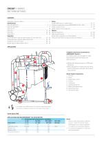
Complete overpressure protection for ASME B&PVC Section I A complete safety valve package for utility and industrial steam generators and steam systems. • Boilers with design pressures to 3000 psig (207 barg). • Valves designed to increase plant up-times, extend maintenance intervals and increase total valve life. Steam System Components 7. Boiler feed water pump 8. Cold reheat inlet VALVE SELECTION APPLICATIONS AND RECOMMENDED™ VALVE SELECTION NOTES 1. Selection matrix shows valves in optimum locations - Styles HSJ and HCI may be interchanged to suit a specific application or to obtain a more...
Open the catalog to page 2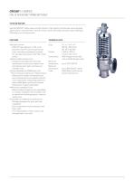
STYLE HE ISOFLEX® Style HE ISOFLEX® safety valves are high pressure, high capacity reaction type valves designed specifically for saturated steam service on boiler drums with design pressures above 2000 psig (138 barg) up to critical pressure. FEATURES TECHNICAL DATA • Extends Up-time - ISOFLEX® seat tightness to 93% of set pressure ensures maximum generating times, extending maintenance intervals. For seat tightness greater than 93% consult factory. • Reduces Maintenance Costs - Exceptional seat tightness minimizes maintenance resources and repair times and reduces spare parts purchase and inventory...
Open the catalog to page 3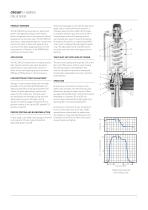
PRODUCT OVERVIEW The HE ISOFLEX incorporates our latest field proven seat tightness design which allows boilers to operate close to set pressure without leakage across the valve seat. The HE ISOFLEX also has a unique patented eductor control that permits the valve to attain full capacity lift at a pressure 3% above popping pressure to the requirements of Section I of the ASME Boiler and Pressure Vessel Code. APPLICATION The HE ISOFLEX safety valve is a high pressure, high capacity reaction type valve, designed specifically for saturated steam service on boiler drums having design pressures above...
Open the catalog to page 4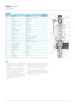
CROSBY H-SERIES STYLE HE ISOFLEX 28 Part name Body Nozzle Nozzle ring Nozzle ring set screw Disc insert Disc holder Disc holder retaining nut Eductor Guide ring Guide ring set screw Spindle assembly Piston Piston retaining ring Spindle nut Bonnet Bonnet studs Bonnet stud nuts Material Carbon steel SA-216 Gr. WCC Stainless steel Stainless steel Stainless steel Inconel® Nickel alloy Stainless steel Nickel alloy Stainless steel Stainless steel Stainless steel Nickel alloy Steel Steel Carbon steel SA-216 Gr. WCC Alloy steel SA-193 Gr. B7 Steel SA-194 Gr. 2H Bottom spring washer Top spring washer...
Open the catalog to page 5
2500 psig maximum pressure 1. These style designations are for standard welded inlets. For optional CL 2500 flanged inlet valves, the "W" is dropped from the style designation. 2. Weld prep per customer's specifications. Safety valves must be mounted on a nozzle with an inlet diameter equal to or greater than the nominal valve inlet size, dimension A. See ASME boiler and pressure vessel code Section I and ANSI/ASME B31.1 for recommended installation. 3. Bolt holes straddle centerline on flanged connections. 4. Dismantling height: an additional 20 inches (508 mm) is required. Drain: main valve...
Open the catalog to page 6
1 Increases Operating Efficiency Sizes: - Restricted Lift Option for customized capacity, reduced reaction forces, and boiler design standardization Orifices: - Seat tightness up to 93% of valve set pressure. For seat tightness greater than Connections: 93% consult factory - Two ring control to adjust overpressure and Maximum blowdown independently temperature: - May also be used for ASME Boiler and Maximum Pressure Vessel Code Section VIII off boiler set pressure: steam applications for higher operating Codes: pressures 1 Reduces Maintenance Costs CROSBY H-SERIES STYLE HCI ISOFLEX DIRECT SPRING...
Open the catalog to page 7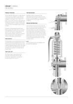
CROSBY H-SERIES STYLE HCI ISOFLEX PRODUCT OVERVIEW The HCI ISOFLEX safety valve is a high capacity nozzle type valve suitable for saturated and superheated steam service. The valves are available in inlet sizes of 1½”, 2", 2½”, 3", 4" and 6" and in orifice sizes H2 to RR specifically designed for the power industry. Welded inlets and flanged outlets are standard, with flanged inlets (1) with full (removable) nozzles (2) also available. Blowdown control is precise with two adjustable rings (3 and 12) - one each on the nozzle (1B or 2) and guide (11). Blowdown may be adjusted from 2 to 4% under...
Open the catalog to page 8
Part ref. Material and maximum temperature Spare parts 8123 Lift stop Stainless steel Stainless steel Stainless steel 9 Disc holder retainer Stainless steel Stainless steel Stainless steel 1 cotter 102 Lift stop cotter Stainless steel Stainless steel Stainless steel 1 11 Guide Nickel alloy Nickel alloy Nickel alloy 2 12 Guide ring Stainless steel Stainless steel Stainless steel 3 13 Guide ring set screw Stainless steel Stainless steel Stainless steel 14 Spindle assembly Stainless steel Stainless steel Stainless steel 2 15 Spring Alloy steel Alloy steel High temp. Corrosion Corrosion alloy steel...
Open the catalog to page 9All Emerson Automation Solutions - TESCOM catalogs and technical brochures
 26-2000 Series
16 Pages
 44-1300 Series
6 Pages
 WEGA-SP
4 Pages
 26-2300 SERIES
4 Pages
 100-625 Pressure Transducers
4 Pages
 DH-16 SERIES
4 Pages
 20-1200 SERIES
4 Pages
 PS-3400 SERIES
4 Pages
 Asset Management Tag
6 Pages
 SG1 SERIES
8 Pages
 56 SERIES
4 Pages
 50-4000 SERIES
4 Pages
 44-3200 SERIES
6 Pages
 26-1000 SERIES
6 Pages
 26-2300 series
4 Pages
 44-2200 Series
4 Pages
 ER5000 Series
12 Pages
 44-1300F Series
4 Pages
 Level
Level3 Pages
 Wireless Overview
1 Page
 Flow Overview
2 Pages
 Temperature Overview
2 Pages
 Pressure Overview
3 Pages
 Product Catalog - 2015
660 Pages