- Catalogs
- Emerson Automation Solutions - ROSEMOUNT
- Flue Gas Analysis as a Boiler Diagnostic Tool
- Products
- Catalogs
- News & Trends
- Exhibitions
Flue Gas Analysis as a Boiler Diagnostic Tool
1 /8Pages

Flue Gas Analysis as a Boiler Diagnostic Tool
1 /8Pages
Catalog excerpts

Application Data Sheet Flue Gas Analysis as a Boiler Diagnostic Tool Overview, and Traditional Application Combustion flue gas analysis has been used by Power Plant Operators for decades as a method of optimizing fuel/air ratio. By measuring the amount of excess oxygen and/or CO in the flue gases resulting from combustion, plant operators can operate at the best heat rate efficiency, lowest NOx, and also generate the least amount of greenhouse gas. The theoretical ideal, or the stoichiometric point, is where all fuel is reacted with available oxygen in the combustion air, and no fuel or O2 is left over. Figure 2 - CFD depiction of the turbulent mixing of fuel and air through a burner. Air-to-Fuel Mixture Area of Maximum Combustion Efficiency CO Due to Poor Mixing of Air and Fuel Rich (Deficient Air) Stoichiometric Point Figure 1 - Key flue gas measurements relating to ideal combustion stoichiometry. Operating furnaces never attain this ideal, however, and the best operating point usually will result in 1–3 % excess air, and 0–200 PPM of CO. This optimum operating point is different for every boiler, and also varies for differing loads, or firing rates. A higher firing rate induces greater turbulence through the burner(s), providing better mixing of fuel and air, and enabling operation with a lower excess O2 before unburned fuel (represented by CO) appears, or “breaks through”. Figure 3 - DCS trend depicting the relationship of O2 and CO indications at CO breakthrough point.
Open the catalog to page 1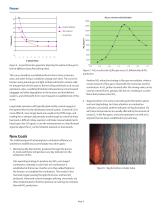
Power NOX as a Function of Air/Fuel Ratio Actual Data Original Setpoint % Steam Flow Figure 4 - a typical function generator depicting the optimum flue gas O2 level at different steam flows (firing rates). This curve should be reestablished from time to time as burners wear, and other furnace conditions change over time. The curve for burners using natural gas and light oil fuels will tend to remain valid for long periods of time (years). Burners firing solid fuels such as coal, petroleum coke, or pelletized biofuels will experience more frequent pluggage and other degradation in the burners...
Open the catalog to page 2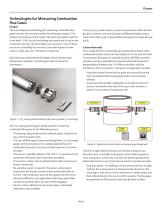
Technologies for Measuring Combustion Flue Gases Oxygen The most ubiquitous technology for measuring combustion flue gases has been the zirconium oxide fuel cell oxygen analyzer. This analyzer technology was first used in the power generation industry in the early 1 970s, but the technology has transferred to use for any combustion process. All automobiles now use one or more of these sensors for controlling fuel-air ratios, and small engines for lawn mowers, chain saws, etc. will soon be using them. Much has been written about the details of how the Nernstian phenomenon operates1, and this paper...
Open the catalog to page 3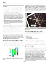
Power Any optical technology presents application challenges that need to be considered: - An extractive system involves transporting and filtering the sample flue gases, removing the moisture, and returning the sample to the process or to a safe vent. This adds considerable cost to the system, and will require significant maintenance attention if there is particulate in the flue gases. - An across duct line-of-sight system cannot be placed where temperatures are much above 600 °C, nor endure high levels of particulate. Thermal growth of the ductwork and vibration can negatively impact the alignment...
Open the catalog to page 4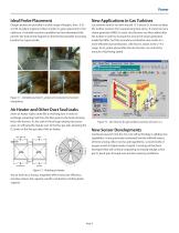
Ideal Probe Placement Oxygen probes are provided in a wide range of lengths, from .5 M to 6 M, but plant engineers often wonder if a given placement is the optimum. A variable insertion capability has been developed that permits the Instrument Engineer to find the best possible mounting location for a given probe. Figure 7 7 - Variable insertion 02 probes in horizontal and vertical Air Heater and Other Duct Seal Leaks Some air heater styles rotate like a revolving door in order to exchange remaining heat from the flue gases to the fresh air being fed to the burners. As the seals in these large...
Open the catalog to page 5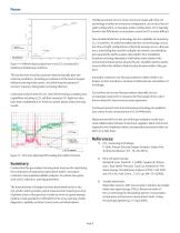
Power The Measurement of CO is most commonly made with infra red technology in either an extractive configuration, across duct line-of– sight configuration, or dual pass probe configuration. CO is typically found in low PPM levels, so automatic control on CO is more difficult. New tunable diode laser technology has the capability of measuring O2, CO and NOx. As with the traditional Infra-red technology, across duct line-of-sight configurations inherently average across a flue gas duct, minimizing the need for multiple instruments, but affording poor granularity within a given optical path. New...
Open the catalog to page 6
www.RosemountAnalytical.com www.analyticexpert.com ©2014 Emerson Process Management. All rights reserved. Emerson Process Management Rosemount Analytical Inc. Gas Analyzer Service Center 6565P Davis Industrial Parkway Solon, OH 44139 USA T +1 440 914 1261 T +1 855-724-2638 (855 RAI-AND-U) Toll Free in US and Canada 800 433 6076 F +1 440 914 1262 US Response Center 800 654 7768 [email protected] The Emerson logo is a trademark and service mark of Emerson Electric Co. Rosemount Analytical is a mark of one of the Emerson Process Management family of companies. All other marks are the property...
Open the catalog to page 8All Emerson Automation Solutions - ROSEMOUNT catalogs and technical brochures
 VPS 53 Vapor Pressure Sensor
2 Pages
 EasyHeat™ XD Cable Kits
2 Pages
 FRL Accessories
14 Pages
 TankRadar Pro
32 Pages
 Rosemount™ 2140 Level Detector
22 Pages
 Roxar subsea PIG
2 Pages
 Roxar subsea Sand monitor
2 Pages
 Roxar subsea CM10K
2 Pages
 Roxar PTPT15K
2 Pages
 Rosemount TankRadar OFC
2 Pages
 SW-300
4 Pages
 DL8000
12 Pages
 DeltaV Analyze
8 Pages
 AMS Machine Works
4 Pages
 DeltaV Executive Portal
7 Pages
 1500XA Gas Chromatograph
8 Pages
 Rosemount 975UR
4 Pages
 Rosemount 975HR
4 Pages
 Rosemount 975UF
4 Pages
 Rosemount 975MR
4 Pages
 CT5400 Process Gas Analyzer
4 Pages
 CT2211 Leak Detection System
4 Pages
 Desalination of Seawater
2 Pages
 700XA Process Gas Chromatograph
12 Pages
 SafeGuard Alarm Controller
2 Pages
 Safety Monitoring
6 Pages
 AMS Suite
16 Pages
 Drinking Water Sht 2V2
2 Pages
 Line Card
2 Pages
 Drinking Water Industry
16 Pages
 Explosion Proof Video Camera
2 Pages
 Net Safety UV Flame Detector
4 Pages


Archived catalogs
 UV/IRS Flame Detector
4 Pages
 UVS Flame Detector
4 Pages

- Bourn And Koch flow meter
- Bourn And Koch volume flow meter
- Bourn And Koch liquid flow meter
- Bourn And Koch concentration analyzer
- Bourn And Koch pressure transmitter
- Bourn And Koch liquids analyzer
- Bourn And Koch pressure gauge
- Bourn And Koch calibrator
- Bourn And Koch analog pressure transmitter
- Bourn And Koch gas flow meter
- Bourn And Koch benchtop analyzer
- Stainless steel flow monitor
- Bourn And Koch industrial flow meter
- Bourn And Koch analog pressure gauge
- Bourn And Koch pressure sensor
- Gas detector
- Bourn And Koch process analyzer
- Bourn And Koch portable analyzer
- Bourn And Koch waterproof pressure transmitter