- Catalogs
- Emerson Automation Solutions - ROSEMOUNT
- Fisher 646 Electro-Pneumatic Transducer
- Products
- Catalogs
- News & Trends
- Exhibitions
Fisher 646 Electro-Pneumatic Transducer
1 /20Pages

Fisher 646 Electro-Pneumatic Transducer
1 /20Pages
Catalog excerpts
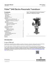
Instruction Manual Fisher™ 646 Electro‐Pneumatic Transducer Contents Introduction . . . . . . . . . . . . . . . . . . . . . . . . . . . . . . . . . 1 Scope of Manual . . . . . . . . . . . . . . . . . . . . . . . . . . . . . 1 Description . . . . . . . . . . . . . . . . . . . . . . . . . . . . . . . . . 3 Specifications . . . . . . . . . . . . . . . . . . . . . . . . . . . . . . . 4 Educational Services . . . . . . . . . . . . . . . . . . . . . . . . . 4 Installation . . . . . . . . . . . . . . . . . . . . . . . . . . . . . . . . . . 4 Hazardous Area Classifications and Special Instructions for “Safe Use” and Installation in Hazardous Locations . . . . . . . . . . . 5 Mounting . . . . . . . . . . . . . . . . . . . . . . . . . . . . . . . . . . 5 Pneumatic Connections . . . . . . . . . . . . . . . . . . . . . . 5 Supply Pressure Requirements . . . . . . . . . . . . . 6 Diagnostic Connections . . . . . . . . . . . . . . . . . . . 7 Vent . . . . . . . . . . . . . . . . . . . . . . . . . . . . . . . . . . . 7 Electrical Connections . . . . . . . . . . . . . . . . . . . . . . . . 7 Operating Information . . . . . . . . . . . . . . . . . . . . . . . . . 9 Calibration . . . . . . . . . . . . . . . . . . . . . . . . . . . . . . . . . 9 Equipment Required . . . . . . . . . . . . . . . . . . . . . . 9 Calibration Procedure . . . . . . . . . . . . . . . . . . . . . 9 Principle of Operation . . . . . . . . . . . . . . . . . . . . . . . . 10 Maintenance . . . . . . . . . . . . . . . . . . . . . . . . . . . . . . . . 11 Troubleshooting . . . . . . . . . . . . . . . . . . . . . . . . . . . . 12 Converter Module Replacement . . . . . . . . . . . . . . 12 Relay Maintenance . . . . . . . . . . . . . . . . . . . . . . . . . . 13 Parts Ordering . . . . . . . . . . . . . . . . . . . . . . . . . . . . . . . 15 Parts List . . . . . . . . . . . . . . . . . . . . . . . . . . . . . . . . . . . 15 Parts Kits . . . . . . . . . . . . . . . . . . . . . . . . . . . . . . . . . . . 15 Figure 1. Fisher 646 Electro‐Pneumatic Transducer Mounted on a Sliding‐Stem Actuator Introduction Scope of Manual This instruction manual provides installation, operation, maintenance, and parts ordering information for the Fisher 646 transducer. Refer to separate manuals for instructions covering equipment used with the transducer. Do not install, operate or maintain a 646 electro‐pneumatic transducer without being fully trained and qualified in valve, actuator and accessory installation, operation and maintenance. To avoid personal injury or property damage it is important to carefully read, understand, and follow all of the contents of this manual, including all safety cautions and warnings. If you have any questions about these instructions, contact your Emerson Process Management sales office before proceeding.
Open the catalog to page 1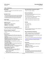
Instruction Manual Table 1. Specifications Input Signal Operating Ambient Temperature Limits(1) 4-20 mA DC, constant current with 30 VDC maximum compliance voltage Equivalent Circuit CSA—Intrinsically Safe, Explosion proof, Type n, Dust‐Ignition proof, DIV 2 The 646 equivalent circuit is a series circuit consisting of a constant voltage drop (battery) of approximately 2.1 VDC and a total resistance of 143 ohms. Input is shunted by three 6.8 V zener diodes (see figure 6). FM—Intrinsically Safe, Explosion proof, Type n, Non‐incendive, Dust‐Ignition proof ATEX—Intrinsically Safe, Flameproof, Type...
Open the catalog to page 2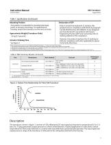
Instruction Manual Table 1. Specifications (Continued) Declaration of SEP Mounting Position Any position is acceptable for standard pipestand, panel, or actuator mounting. For weatherproof housing, mount the transducer so the vent can drain. Fisher Controls International LLC declares this product to be in compliance with Article 4 paragraph 3 of the PED Directive 2014/68/EU. It was designed and manufactured in accordance with Sound Engineering Practice (SEP) and cannot bear the CE marking related to PED compliance. Approximate Weight (Transducer Only) 1.6 kg (3.5 pounds) However, the product...
Open the catalog to page 3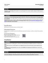
CAUTION Dropping or rough handling of the transducer can cause damage to the converter module resulting in a shifted output or a minimum output. WARNING This product does not meet third party approvals (CSA, FM, ATEX, or IECEx) for use with natural gas as the supply medium. Use of natural gas as the supply medium can damage the instrument and result in personal injury or property damage from fire or explosion. Should you need an instrument for use with natural gas, Fisher 846 and i2P‐100 electro‐pneumatic transducers both meet third party approvals for use with natural gas as the supply medium....
Open the catalog to page 4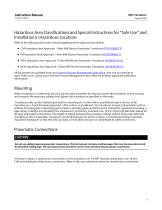
Hazardous Area Classifications and Special Instructions for “Safe Use” and Installation in Hazardous Locations Refer to the following instruction manual supplements for approval information. D CSA Hazardous Area Approvals Fisher 646 Electro-Pneumatic Transducer (D104199X012) D FM Hazardous Area Approvals Fisher 646 Electro-Pneumatic Transducer (D104200X012) D ATEX Hazardous Area Approvals Fisher 646 Electro-Pneumatic Transducer (D104201X012) D IECEx Hazardous Area Approvals Fisher 646 Electro-Pneumatic Transducer (D104202X012) All documents are available from your Emerson Process Management sales...
Open the catalog to page 5
Instruction Manual Figure 3. Dimensions and Connections 152.4 (6.00) OPTIONAL GAUGE 1/4‐18 NPT OPTIONAL OUTPUT OR GAUGE CONN Supply Pressure Requirements WARNING Severe personal injury or property damage may occur if the instrument air supply is not clean, dry and oil‐free. While use and regular maintenance of a filter that removes particles larger than 40 micrometers in diameter will suffice in most applications, check with an Emerson Process Management field office and industry instrument air quality standards for use with corrosive air or if you are unsure about the proper amount or method...
Open the catalog to page 6
Instruction Manual Diagnostic Connections To support diagnostic testing of valve/actuator/positioner packages, special connectors and hardware are available. Typical connector installations are shown in figure 4. The hardware used includes a 1/4 NPT pipe nipple and pipe tee with a 1/8 NPT pipe bushing for the connector. The connector consists of a 1/8 NPT body and body protector. Figure 4. Diagnostics Hookup for the Fisher 646 Transducer STEM PROVIDED WHEN GAUGE IS SPECIFIED BODY PROTECTOR BODY BODY PROTECTOR PIPE BUSHING PIPE BUSHING FRONT OUTPUT SIDE OUTPUT PIPE NIPPLE Note If the 646 transducer...
Open the catalog to page 7All Emerson Automation Solutions - ROSEMOUNT catalogs and technical brochures
 VPS 53 Vapor Pressure Sensor
2 Pages
 EasyHeat™ XD Cable Kits
2 Pages
 FRL Accessories
14 Pages
 TankRadar Pro
32 Pages
 Rosemount™ 2140 Level Detector
22 Pages
 Roxar subsea PIG
2 Pages
 Roxar subsea Sand monitor
2 Pages
 Roxar subsea CM10K
2 Pages
 Roxar PTPT15K
2 Pages
 Rosemount TankRadar OFC
2 Pages
 SW-300
4 Pages
 DL8000
12 Pages
 DeltaV Analyze
8 Pages
 AMS Machine Works
4 Pages
 DeltaV Executive Portal
7 Pages
 1500XA Gas Chromatograph
8 Pages
 Rosemount 975UR
4 Pages
 Rosemount 975HR
4 Pages
 Rosemount 975UF
4 Pages
 Rosemount 975MR
4 Pages
 CT5400 Process Gas Analyzer
4 Pages
 CT2211 Leak Detection System
4 Pages
 Desalination of Seawater
2 Pages
 700XA Process Gas Chromatograph
12 Pages
 SafeGuard Alarm Controller
2 Pages
 Safety Monitoring
6 Pages
 AMS Suite
16 Pages
 Drinking Water Sht 2V2
2 Pages
 Line Card
2 Pages
 Drinking Water Industry
16 Pages
 Explosion Proof Video Camera
2 Pages
 Net Safety UV Flame Detector
4 Pages


Archived catalogs
 UV/IRS Flame Detector
4 Pages
 UVS Flame Detector
4 Pages

- Bourn And Koch flow meter
- Bourn And Koch volume flow meter
- Bourn And Koch liquid flow meter
- Bourn And Koch gas analyzer
- Bourn And Koch concentration analyzer
- Bourn And Koch pressure transmitter
- Bourn And Koch liquids analyzer
- Bourn And Koch pressure gauge
- Bourn And Koch calibrator
- Bourn And Koch analog pressure transmitter
- Bourn And Koch gas flow meter
- Bourn And Koch benchtop analyzer
- Bourn And Koch stainless steel flow meter
- Bourn And Koch industrial flow meter
- Bourn And Koch analog pressure gauge
- Bourn And Koch pressure sensor
- Gas detector
- Bourn And Koch process analyzer
- Bourn And Koch portable analyzer
- Bourn And Koch waterproof pressure transmitter