Scroll Installation Instructions
1 /35Pages

Scroll Installation Instructions
1 /35Pages
Catalog excerpts

INSTALLATION INSTRUCTIONS FOR EMBRACO SCROLL REFRIGERATION COMPRESSORS
Open the catalog to page 1
Use only approved re*-| Manufacturer. For detj tires, explosions. o> • • SCOPE OF THE COMPRESSOR INSTALLATION INSTRUCTIONS These installation instructions applies to Embraco scroll compressors for refrigeration applications. The Country of Origin is indicated on the compressor label. It is addressed to professional, commercial refrigeration system manufacturers/installers and maintenance technicians and intends to provide instructions/recommendations on the proper use of Embraco scroll compressors regarding reliability, performance and safety aspects. The information of this these installation...
Open the catalog to page 2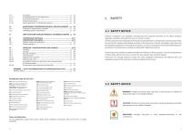
12 MAINTENANCE (COMPRESSOR REMOVAL AND REPLACEMENT) ..p. 53 13 HOW TO RETURN SUPPLIED PRODUCTS TO EMBRACO EUROPE . p. 56 16.4.3 Acceptable compressor positions during transportation ACRONYMS USED IN THE TEXT ATEL: Acute-toxicity Exposure Limit AHRI: Air-Conditioning, Heating and Refrigeration Institute (formerly) CSR (CSCR): Capacitive Start & Run (Capacitor Start - Capacitor Run) DTC: Discharge Temperature Control Valve EN: European Standards GFCI: Ground Fault Circuit Interrupter GWP: Global Warming Potential HFC: HydroFluoroCarbon HFO: HydroFluoroOlefin ID: Internal Diameter IP: International...
Open the catalog to page 4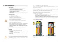
1.3 SAFETY INSTRUCTIONS Safety statements • Refrigerant compressors must be used only for their intended use. • Only qualified/certified and authorized refrigeration technicians are permitted to perform installation and maintenance of compressors. • Electrical connections must be made by qualified electrical technicians. • All valid standards for installing, servicing, and maintaining of electrical and refrigeration equipment must be observed. • Usage of personal safety equipment is recommended (goggles, gloves, clothing, boots and hard hats) Electrical shock hazard • Turn off power before servicing....
Open the catalog to page 5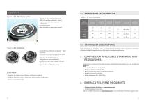
DESIGN FEATURES 2.1 COMPRESSOR TEST CONDITION Table 2.1 Test condition Dynamic valve specially designed for MBP/LBP working conditions - allows high compression ratio reducing compression. Instant shutdown. More efficient for pump down control. 2.2 COMPRESSOR COOLING TYPES Unique design with dual compliance - radial and axial. Effective control of discharge temperature to improve compressor reliability. Specially designed for Mid/Low temperatures compression ratio. Height-thickness ratio to assure strength of involutes. High isentropic efficiency design. 2.0.3 Motor • Designed for higher motor...
Open the catalog to page 6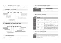
Information printed on compressor label: model, voltage and frequency supply, bill of material. 5. COMPRESSOR NOMENCLATURE5.2.2 VOLTAGE AND FREQUENCY SUPPLY Table 5.2.2 VOLTAGE CODE 5.1 COMPRESSOR MODEL CODE 5.2.3 EXTERNAL EXECUTION Table 5.2.3 In Btu/h at 60 Hz x 1000 ARI conditions E.g. 015=15000 Btu/h 5.2 COMPRESSOR BILL OF MATERIAL CODE EXTERNAL EXECUTION 5.2.4 ELECTRICAL EXECUTION Table 5.2.4 5.2.1 COMPRESSOR SIZE 1 - MBP models for 2-6hp 2 - MBP models for 7-13hp
Open the catalog to page 7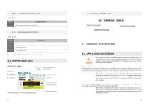
5.3.1 SERIAL NUMBER CODE 5.2.5 ACCESSORIES EXECUTION Table 5.2.5 EXECUTION CONFIGURATION TYPE Grommets, sleeves, tube plug, DTC valve included for LBP PRODUCTION LINE 5.2.6 PACKAGING EXECUTION Table 5.2.6 EXECUTION Note: See Chapter 15 for detailed information about packaging. 5.3 COMPRESSOR LABEL Figure 5.3 Label Oil type Oil initial charge Maximum Operating Pressures (Low and High Side) Compressor model Bill of Materials code Serial Number Code* Compressor protection Displacement Each compressor model is intended for specific refrigerant and application. Their use in different application and/or...
Open the catalog to page 8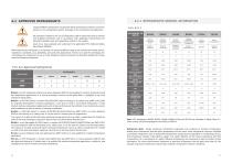
6.2.1 REFRIGERANTS GENERAL INFORMATION I Usage of different refrigerants can generate abnormal working conditions, excessive pressure in the refrigeration system, damages of the compressor and explosions. All operations related to the use of refrigerants shall be performed only by trained and qualified technicians and in accordance with applicable International and National standards, laws and regulations related to this subject. Users must have available and understand the applicable HFCs Material Safety Data Sheets (MSDSs). When selecting the refrigerant, it is important to measure different...
Open the catalog to page 9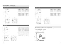
BRAZING I.D. mm MATERIAL S - SUCTION 22.35-22.45 COPPER PLATED STEEL D - DISCHARGE 12.87-12.97 COPPER PLATED STEEL L - LIQUID INJ. 3/8" COPPER PLATED STEEL ROTOLOCK I.D. inches MATERIAL S - SUCTION 1 1/4" 12UNF 2A STEEL 6.4 HERMETIC TERMINAL DIMENSIONS 18
Open the catalog to page 10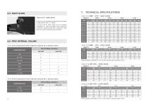
7. TECHNICAL SPECIFICATIONS COMPRESSOR SIZE 2 - 3 HP 3.5 - 4 HP Testing conditions: EN12900 Te -35°C; Tc 40°C; Rg 20°C; No subcooling; Ta 35°C
Open the catalog to page 11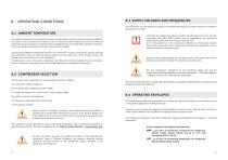
8.3 SUPPLY VOLTAGES AND FREQUENCIES The compressor must be selected according to the voltage and frequency conditions where the installation will operate in the field. 8.1 AMBIENT TEMPERATURE The ambient temperature surrounding the system strongly influences the compressor working conditions. The system must be designed and tested in order to ensure that the compressor works (at normal and abnormal expected conditions in the field) within its admitted limits (see Chapter 8.4 - Operating envelopes) at the max ambient temperature where the system will be installed. A functional and efficient refrigeration...
Open the catalog to page 12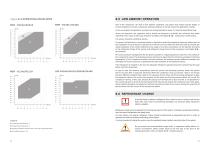
Figure 8.4 OPERATING ENVELOPES Even if the compressor can work in low ambient conditions, the system may require specific design or recommendations to ensure compressor working conditions to remain inside the application envelop. In the low ambient temperature, normally, the cooling load will be lower. To avoid the liquid flood back . during the operation, the expansion device should be designed to maintain the minimum and stable superheat. Short cycle of start/stop should be avoided, see Chapter 8.10 - Compressor On/off cycling. The system should be verified by testing. To prevent the flood...
Open the catalog to page 13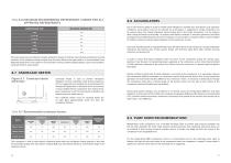
Table 8.6 MAXIMUM RECOMMENDED REFRIGERANT CHARGE FOR ALL APPROVED REFRIGERANTS The compressor is safe to start without crankcase heater when the refrigerant charge quantity is less than recommended charge limit (see Table in Chapter 8.6). but nevertheless Embraco recommends usage of the crankcase heater. 8.9 PUMP DOWN RECOMMENDATIONS Refrigeration scroll compressors use a low-leak discharge valve to prevent high pressure backflow into the low side. Typically, this check valve prevents system pressures from equalizing and pump down can be achieved. If short cycling cannot be avoided, using a 3-minute...
Open the catalog to page 14All EMBRACO catalogs and technical brochures
 Ice Machine (X Generation)
5 Pages
 COMPRESSORS EUROPE
61 Pages
Archived catalogs
 BIOMA
BIOMA23 Pages
 Condensing Units_2017
47 Pages
 Aftermarket Line of Products
16 Pages
 Scroll Compressors
37 Pages
 Heat Exchangers
2 Pages
 A B G Product Line for R 22
6 Pages
 Condensing Units_2008
26 Pages
 A B G Product Line for R 22
6 Pages
 Gemini
8 Pages
 A and B Product Line
6 Pages
 Embraco Condensing Units
3 Pages
 Heat Exchangers
2 Pages
 Cooling Solutions
2 Pages
 Electrical Components Aspera
20 Pages
 Compressor Application Manual
79 Pages
 Compressor Handbook
100 Pages
 Embraco Company and Products
6 Pages


- AMOT refrigeration compressor
- AMOT hermetic refrigeration compressor
- AMOT piston refrigeration compressor
- AMOT single-stage refrigeration compressor
- Condensing unit
- Air-cooled condensing unit
- AMOT commercial refrigeration refrigeration compressor
- Variable-speed refrigeration compressor
- Hermetic condensing unit
- Industrial condensing unit
- Air conditioning refrigeration compressor