


Condensing Units_2008

Condensing Units_2008
This document details Embraco Condensing Units designed for North American applications, ranging from 1/6 HP to 5 HP. These units are suitable for commercial freezers and refrigerators and compatible with refrigerants like R 22, R 134a, and R 404A.
The units feature reliable hermetic compressors, corrosion-resistant materials, and customizable designs. High horsepower models include Rotalock valves and pressure controls.
Proper installation is essential for optimal performance and warranty assurance. Key steps include inspecting for damage, ensuring ventilation, and following procedures for soldering, leakage detection, and system evacuation.
1. Select and size equipment according to specifications.
2. Solder piping and perform leak tests.
3. Evacuate the system and charge refrigerant.
4. Monitor system pressures and temperatures.
5. Adjust for continuous operation.
Mandatory cleaning before installation using R 141b for flushing and a filter-dryer to remove contaminants.
Use nitrogen to prevent oxidation during brazing and limit exposure of sensitive components to air.
Use nitrogen for pressurization and electronic or soap bubble methods for leak detection.
Use a high vacuum pump and avoid using the compressor for evacuation.
Charge refrigerant in liquid form after achieving proper vacuum, ensuring even distribution before operation.
Ensure flexibility, proper refrigerant distribution, and oil return. Use inverted siphons and suction accumulators as needed.
Include filter-dryers, sight glasses, solenoid valves, expansion valves, suction accumulators, oil separators, suction filters, crankcase heaters, and pressure switches.
Verify electrical ratings and follow wiring diagrams for proper connections. Ensure grounding to prevent electrocution.
- Temperature Categories: H = Medium/High, M = Medium, L = Low.
- Refrigerant Options: R 22, R 404A.
- Compressor Families: A and B.
- Capacity: 11,000 Btu/h.
- Voltage Options: 230/208V - 1~60Hz, 230/208V - 3~60Hz (220/200V - 3~50Hz).
- Application: Standard includes Pressure Switch, Receiver, Suction and Discharge Valve. Optional accessories include Filter Drier, Sight Glass, Suction Accumulator, Electrical Box.
Embraco is a participant in the United Nations Global Compact. Offices are located in Brazil, Italy, Slovakia, U.S.A., China, and Mexico. Website: www.embraco.com
Catalog excerpts

Index embrace 3 - Technical Instructions / Installation Precautions 02 3.2 - Basic Installation - Overview 02 3.5 - Recommendations for Brazing (welding) the System 03 3.8 - Procedures for Refrigerant Charge 04 3.10 - Basic Accessories of a Cooling System 05 Warning All data is subject to change without notice.
Open the catalog to page 2
Condensing Unit 1) - General High Horse Power Units (from 1 to 5 HP) This catalog contains information on Embraco Condensing Units designed specifically for application in North America. • Rotalock valve The line of Embraco Condensing Units was designed in accordance with the strictest quality and reliability standards, available for a wide range of applications, varying from 1/6 HP to 5 HP in medium, low and high evaporating temperature applications, with R 22, R 134a, R 12/replacement refrigerants and R 404A. • Electrical conduit • Service valve • Fan guard • Pressure controls • Liquid receiver...
Open the catalog to page 3
18°F (5°C and 10°C). Superheating at the compressor’s inlet must be between 18°F and 27°F (10°C and 15°C) (for this case, the difference between the temperature at the surface of the return pipe, at a distance 6" (150 mm) from the compressor, and the evaporation temperature. The sub-cooling in the condenser shall be between 5°F and 18°F (3°C and 10°C), i.e., the condensing temperature less the temperature at the pipe's surface at the condenser's outlet. * Evaporation temperature obtained by converting the suction pressure into temperature. It is important that all items are monitored according...
Open the catalog to page 4
Condensing Unit 3.8) - Procedures for Refrigerant Charge soap bubbles The refrigerant shall only be charged after the proper vacuum has been achieved. Please check on the compressor or condensing unit tag what is the type of refrigerant that should be used to charge the system. Break the vacuum only when the compressor is switched off. It is recommended that the refrigerant charge be provided in the liquid state (with the compressor switched off), through the high side (tank liquid valve) and by the refrigerant mass measurement (lb), according to the system specification. Wait for 15 minutes...
Open the catalog to page 5
3.9.3 - Prevent the liquid from flowing back to the compressor when the system stops and the evaporator(s) is/are located above the Condensing Unit, using an inverted siphon and suction accumulator. • Systems with more than one evaporator 3.9.4 - Aid the return of lubricating oil coming from the evaporator(s) to the system where the Condensing Unit is located over 118 inches above the evaporator(s), using an inverted siphon every 118 inches in the piping. • Where the distance from the compressor to the evaporator is over 50 feet (15 meters) 3.9.5 - Allow secondary operations, such as attaching...
Open the catalog to page 6
Condensing Unit Follow the instructions and make the proper connections as depicted in the wiring diagram of each model. start relay brown blue Single-Phase RSIR/CSIR (RELAY) In case a starting capacitor is needed, the connection may be made between terminals 3 and 4 (11 and 13 when the condensing unit use EG/F compressor), just by breaking this jumper. F = Fuse C = Fan capacitor CS = Start capacitor CR = Run capacitor K1 = Contact switch A1/A2 = Contact coil Compressors applied without an Run capacitor use PTC with 1 terminal. MOTOR TYPE CSIR - Capacitive Start Inductive Run CSR - Capacitive...
Open the catalog to page 7
Cross Reference * 25°F (-4°C) Evaporating temperature / 90°F (32°C) Ambient temperature. Other models upon request.
Open the catalog to page 8
Condensing Unit * 25°F (-4°C) Evaporating temperature / 90°F (32°C) Ambient temperature. Other models upon request.
Open the catalog to page 9
* 25°F (-4°C) Evaporating temperature / 90°F (32°C) Ambient temperature. Other models upon request.
Open the catalog to page 10
R 134a - HBP - 60Hz Performance / Evaporating Temperature oF - ASHRAE HP Check Point Data 45oF (7.2oC) Motor Type *MCA - Minimum Circuit Amps | MFS - Maximum Fuse Size | LRA - Locked Rotor Amps R 134a - L/MBP - 60Hz Performance / Evaporating Temperature oF - ASHRAE HP Check Point Data -10oF (-23.3oC) Motor Type Consumption Power *MCA - Minimum Circuit Amps | MFS - Maximum Fuse Size | LRA - Locked Rotor Amps
Open the catalog to page 11
Fan Angle of (diameter) blades Rated Receiver Output LBs Connecting Port (inch) Blade (diameter) Rated Receiver Output LBs Connecting Port (inch)
Open the catalog to page 12
R 22 - HBP - 60Hz Performance / Evaporating Temperature oF - ASHRAE HP Check Point Data 45oF (7.2oC) Motor Type Consumption Power *MCA - Minimum Circuit Amps | MFS - Maximum Fuse Size | LRA - Locked Rotor Amps
Open the catalog to page 13
Blade (diameter) Rated Receiver Output LBs Connecting Port (inch)
Open the catalog to page 14
R 404A - M/HBP - 60Hz Performance / Evaporating Temperature oF - ASHRAE HP Check Point Data 45oF (7.2oC) Motor Type Consumption Power *MCA - Minimum Circuit Amps | MFS - Maximum Fuse Size | LRA - Locked Rotor Amps R 404A - LBP - 60Hz Performance / Evaporating Temperature oF - ASHRAE HP Check Point Data -10oF (-23.3oC) Motor Type Consumption Power *MCA - Minimum Circuit Amps | MFS - Maximum Fuse Size | LRA - Locked Rotor Amps
Open the catalog to page 15
Blade (diameter) Rated Receiver Output LBs Connecting Port (inch) Angle of (diameter) Blades Blade Rated Receiver Output LBs Connecting Port (inch)
Open the catalog to page 16
Performance / Evaporating Temperature °F - ASHRAE Check Point Data 45°F (7.2°C) Power Current *MCA - Minimum Circuit Amps | MFS - Maximum Fuse Size | LRA - Locked Rotor Amps Performance / Evaporating Temperature °F - ASHRAE Check Point Data -10°F (-23.3-C) Power Current *MCA - Minimum Circuit Amps | MFS - Maximum Fuse Size | LRA - Locked Rotor Amps *MCA - Minimum Circuit Amps | MFS - Maximum Fuse Size | LRA - Locked Rotor Amps
Open the catalog to page 17
Fan Angle of (diameter) Blades Connecting Port Rated Receiver Output LBs Fan Angle of (diameter) Blades Rated Receiver Output LBs Connecting Port (inch) Blade (diameter) Rated Receiver Output LBs Connecting Port (inch)
Open the catalog to page 18
R 404A - LBP - 50Hz Performance / Evaporating Temperature oF - ASHRAE HP Check Point Data -10oF (-23.3oC) Motor Type *MCA - Minimum Circuit Amps | MFS - Maximum Fuse Size | LRA - Locked Rotor Amps
Open the catalog to page 19All EMBRACO catalogs and technical brochures
 Ice Machine (X Generation)
5 Pages
 COMPRESSORS EUROPE
61 Pages
Archived catalogs
 BIOMA
BIOMA23 Pages
 Scroll Installation Instructions
35 Pages
 Condensing Units_2017
47 Pages
 Aftermarket Line of Products
16 Pages
 Scroll Compressors
37 Pages
 Heat Exchangers
2 Pages
 A B G Product Line for R 22
6 Pages
 A B G Product Line for R 22
6 Pages
 Gemini
8 Pages
 A and B Product Line
6 Pages
 Embraco Condensing Units
3 Pages
 Heat Exchangers
2 Pages
 Cooling Solutions
2 Pages
 Electrical Components Aspera
20 Pages
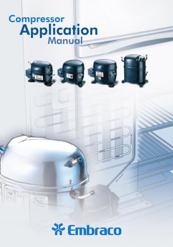 Compressor Application Manual
79 Pages
 Compressor Handbook
100 Pages
 Embraco Company and Products
6 Pages


- Electromotor
- EC motor
- Process software
- Digital temperature control
- Compact electromotor
- Industrial software
- Temperature controller
- Digital temperature controller
- Optimization software
- Fan motor
- Variable-speed motor
- EMBRACO refrigeration compressor
- ERP software solution
- ATEX motor
- IP65 temperature controller
- EMBRACO hermetic refrigeration compressor
- Food motor
- 240 V motor
- Temperature controller with LED display
- EMBRACO R134a refrigeration compressor