
- Catalogs
- Eltra S.p.a.
- EPLA LINEAR POTENTIOMETER

- Company
- Products
- Catalogs
- News & Trends
- Exhibitions
EPLA LINEAR POTENTIOMETER

EPLA LINEAR POTENTIOMETER
Catalog excerpts

EPLALINEAR POTENTIOMETER MAIN FEATURES EPLA is an absolute linear potentiometer assuring great reliability even in tough applications with heavy vibrations and shocks. The groove on the enclosure of the transducer represents an excellent alternative to the usual system of fastening with brackets. Installation is also made simpler by the absence of variations on the electrical output signal outside of the theoretical electrical stroke. EPLA is the right solution in machinery for material processing such as injection presses for plastic, rubber and so on. ORDERING CODE EPLA 200 X 10 C5 SERIES linear potentiometer model EPLA STROKE mm from 50 to 900 see table for stroke availability ENCLOSURE RATING IP 60 X IP 65 S TRAVEL SPEED max speed 10 m/s 10 OUTPUT TYPE cable (standard length 1 m) P 3 pin connector C3 DIN 43650-A 4 pin connector C4 DIN 43322 5 pin connector C5 OUTPUT DIRECTION axial A © Copyright 2016 Eltra S.p.a. Unipersonale. All rights reserved. All informations in this catalog are subject to change without notice. Eltra takes no responsibility for typographic errors. For the terms of sales please check the website. REV. 160607 192
Open the catalog to page 1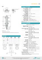
ELECTRICAL SPECIFICATIONS Important: datas are valid if the transducer is used as a ratiometric device with a maximum applicable current < 0,1 pA. ■ fixing kit (brackets, screws) included ■ female connector not included, for ordering P/N please refer to Accessories section MECHANICAL SPECIFICATIONS Installation warning instructions: ■ connect the transducer according to the reported connections ■ DO NOT use it as a variable resistance ■ the transducer calibration has to be done setting the stroke in order to have an output signal between 1% and 99% of the voltage level © Copyright 2016 Eltra...
Open the catalog to page 2All Eltra S.p.a. catalogs and technical brochures
 EMB
EMB3 Pages
 EC 34
EC 343 Pages
 EP A / B
2 Pages
 EMD
EMD2 Pages
 ELASTIC COUPLINGS
3 Pages
 EV B / C
2 Pages
 EMI 30 M
2 Pages
 EF 36 K
2 Pages
 EH - EL 88 P
2 Pages
 EH 99 P
2 Pages
 EL - ER 63 A / D / E
3 Pages
 EL - ER 58 B /C/H/T
3 Pages
 EH - EF 80 C / P / K
2 Pages
 EH 17 - 30 MH
2 Pages
 EH 50 FA / FP
2 Pages
 EL - EF 49 C / P
2 Pages
 EL 120 P
2 Pages
 EL - ER 72 A / B
3 Pages
 EMI 63 A / D
2 Pages
 EMI 55 A / AY
2 Pages
 EMI 40 A
2 Pages
 EL 48 C / P
2 Pages
 EL - ER 38 F / G
2 Pages
 ETMR
ETMR2 Pages
 EL - ER 90 A EL - ER 115 A
3 Pages
 EL - ER 63 AX / DX
2 Pages
 EH 17 - 30 M
2 Pages
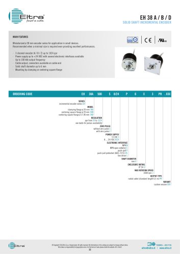 EH 38 A / B / D
2 Pages
 EL - ER 40
3 Pages
 EH 90 A - EH 115 A / R
3 Pages
 EMI 22 A
2 Pages
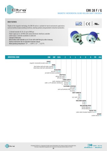 EMI 38 F / G
2 Pages
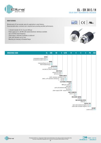 EL - ER 30 E / H
2 Pages
 EMSPA
EMSPA3 Pages
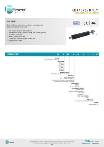 ER A / B / C / D / E / F
2 Pages
 EMSSA
EMSSA3 Pages
 EPLC
EPLC2 Pages
 EBMA
EBMA2 Pages
 EMSSS
EMSSS3 Pages
 EMSPS
EMSPS2 Pages
 FES
FES2 Pages
 EMSPB
EMSPB2 Pages
 EPLB
EPLB2 Pages
 ETMA 1 / 2
2 Pages
 FE
FE2 Pages
 EPLT
EPLT2 Pages
 EAX 80 A / D SSI
2 Pages
 AAM 58 B / C PROFINET
3 Pages
 EML 50 A / B / BY ANALOGUE
3 Pages
 EAM 36 F / G SSI
2 Pages
 EA 63 AX / DX SSI
2 Pages
 AAM 58 F PROFINET
3 Pages
 EA 36 A SSI
2 Pages
 EML 50 F / G ANALOGUE
3 Pages
 EMA 55 A / AY SSI
2 Pages
 EAM 63 AX / DX PROFIBUS
2 Pages
 EAM 63 AX / DX SS
2 Pages
 EA 58 F - 63 F / G
2 Pages
 EA 63 AX / DX
2 Pages
 EMA 22 A
2 Pages
 EAM 58 B / C - 63 A / D / E
5 Pages
 EA 58 B / C - 63 A / D / E
3 Pages
 EAMX 80 A / D
3 Pages
 EAM 36 A
2 Pages
 EAM 90 A -115 A
2 Pages
 EA 36 F / G
2 Pages
 EAMW 58 B / C - 63 A / D
3 Pages
 EAM 58 F - 63 F / G
2 Pages
 EA 90 A - 115 A
2 Pages
 EA 58 F - 63 F / G
4 Pages
 EA 58 B / C - 63 A / D / E
4 Pages




- Angular encoder
- Incremental encoder
- Incremental rotary encoder
- Flexible coupling
- Absolute rotary encoder
- Position transducer
- Solid-shaft rotary encoder
- Optical rotary encoder
- Industrial rotary encoder
- Hollow-shaft rotary encoder
- Magnetic rotary encoder
- Linear position transmitter
- Flange coupling
- IP65 rotary encoder
- Compact rotary encoder
- IP67 rotary encoder
- Aluminum rotary encoder
- DC rotary encoder
- Analog position transducer
- Transmission coupling