EMD
1 /2Pages

EMD
1 /2Pages
Catalog excerpts
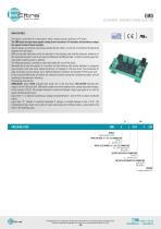
EMDELECTRONIC INTERFACE SIGNAL SELECTOR MAIN FEATURES This board is used when it is necessary to select a signal among a maximum of 3 inputs. The EMD board accepts input signals coming from a maximum of 3 encoders and provides as output the signals of one of these encoders. Output signals are selected connecting properly the two inputs, in1 and in2, according to the operating diagram (see next page). EMD and encoder electronics must be indicated in the ordering code and the electronic interfaces of the connected encoders must be all identical. Moreover the EMD provides 3 contacts normally open that close when respective input is selected. The following example is needful to understand better the use of this board. We would like to read the signals of 3 encoders (or other devices with similar features) in sequential way. Encoders must have same output electronics, for example 5 V DC line driver. The instrument for data acquisition, on the contrary, has a different electronic interface, for example 24 V DC push-pull. In this case the EMD board will perfom the selection function among the connected encoders and the matching of the electronic interfaces. The ordering code will be: EMD5L8/24P, where EMD5L indicates that inputs are 5 V DC line driver, EMD5L8/24P indicates that output is 8^24 V DC push-pull. EMD power supply must be the highest value among requested voltages: in this case 8^24 V DC. The encoder selection is carried out through a logic type signal at ini and in2 inputs on the terminal board. Logic level “1” is obtained connecting a voltage included between 5 and 24 V DC to above mentioned inputs. Logic level “0”, instead, is correctly interpreted if voltage is included between 0 and 3 V DC. The combination of logic levels at ini and in2 inputs sets outputs to 4 different states, as described in the table in the following page. SERIES signal selector EMD INPUT VOLTAGE X1 / X2 / X3 CONNECTOR 5 V DC 5 8 ... 24 V DC 8/24 INPUT ELECTRONICS X1 / X2 / X3 CONNECTOR (8 ...24V) push-pull P line driver L OUTPUT VOLTAGE X4 CONNECTOR 5 V DC 5 8 ... 24 V DC 8/24 OUTPUT ELECTRONICS X4 CONNECTOR push-pull P line driver L VARIANT custom version XXX © Copyright 2016 Eltra S.p.a. Unipersonale. All rights reserved. All informations in this catalog are subject to change without notice. Eltra takes no responsibility for typographic errors. For the terms of sales please check the website. REV. 160607 236
Open the catalog to page 1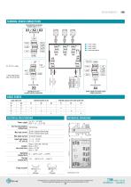
TERMINAL BOARD CONNECTIONS F1, F2, F3 = relay LOGIC STATES ELECTRICAL SPECIFICATIONS MECHANICAL DIMENSIONS © Copyright 2016 Eltra S.p.a. Unipersonale. All rights reserved. All informations in this catalog are subject to change without notice. Eltra takes no responsibility for typographic errors. For the terms of sales please check the website. REV. 160607 237
Open the catalog to page 2All Eltra S.p.a. catalogs and technical brochures
 EMB
EMB3 Pages
 EC 34
EC 343 Pages
 EP A / B
2 Pages
 ELASTIC COUPLINGS
3 Pages
 EV B / C
2 Pages
 EMI 30 M
2 Pages
 EF 36 K
2 Pages
 EH - EL 88 P
2 Pages
 EH 99 P
2 Pages
 EL - ER 63 A / D / E
3 Pages
 EL - ER 58 B /C/H/T
3 Pages
 EH - EF 80 C / P / K
2 Pages
 EH 17 - 30 MH
2 Pages
 EH 50 FA / FP
2 Pages
 EL - EF 49 C / P
2 Pages
 EL 120 P
2 Pages
 EL - ER 72 A / B
3 Pages
 EMI 63 A / D
2 Pages
 EMI 55 A / AY
2 Pages
 EMI 40 A
2 Pages
 EL 48 C / P
2 Pages
 EL - ER 38 F / G
2 Pages
 ETMR
ETMR2 Pages
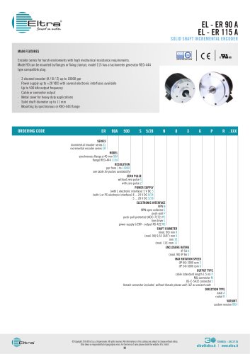 EL - ER 90 A EL - ER 115 A
3 Pages
 EL - ER 63 AX / DX
2 Pages
 EH 17 - 30 M
2 Pages
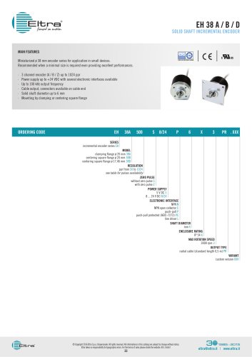 EH 38 A / B / D
2 Pages
 EL - ER 40
3 Pages
 EH 90 A - EH 115 A / R
3 Pages
 EMI 22 A
2 Pages
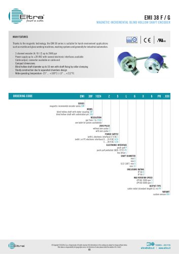 EMI 38 F / G
2 Pages
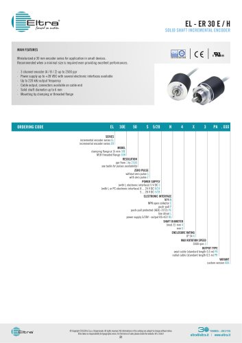 EL - ER 30 E / H
2 Pages
 EMSPA
EMSPA3 Pages
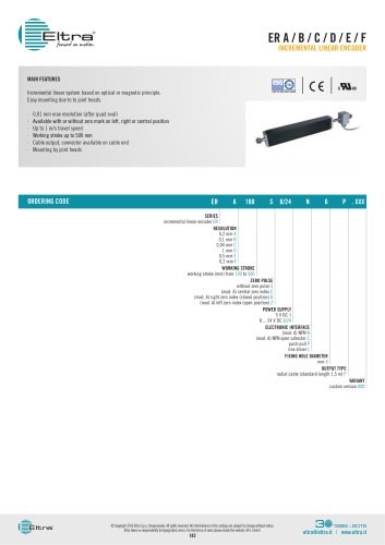 ER A / B / C / D / E / F
2 Pages
 EMSSA
EMSSA3 Pages
 EPLC
EPLC2 Pages
 EBMA
EBMA2 Pages
 EMSSS
EMSSS3 Pages
 EMSPS
EMSPS2 Pages
 FES
FES2 Pages
 EMSPB
EMSPB2 Pages
 EPLB
EPLB2 Pages
 ETMA 1 / 2
2 Pages
 FE
FE2 Pages
 EPLT
EPLT2 Pages
 EPLA LINEAR POTENTIOMETER
2 Pages
 EAX 80 A / D SSI
2 Pages
 AAM 58 B / C PROFINET
3 Pages
 EML 50 A / B / BY ANALOGUE
3 Pages
 EAM 36 F / G SSI
2 Pages
 EA 63 AX / DX SSI
2 Pages
 AAM 58 F PROFINET
3 Pages
 EA 36 A SSI
2 Pages
 EML 50 F / G ANALOGUE
3 Pages
 EMA 55 A / AY SSI
2 Pages
 EAM 63 AX / DX PROFIBUS
2 Pages
 EAM 63 AX / DX SS
2 Pages
 EA 58 F - 63 F / G
2 Pages
 EA 63 AX / DX
2 Pages
 EMA 22 A
2 Pages
 EAM 58 B / C - 63 A / D / E
5 Pages
 EA 58 B / C - 63 A / D / E
3 Pages
 EAMX 80 A / D
3 Pages
 EAM 36 A
2 Pages
 EAM 90 A -115 A
2 Pages
 EA 36 F / G
2 Pages
 EAMW 58 B / C - 63 A / D
3 Pages
 EAM 58 F - 63 F / G
2 Pages
 EA 90 A - 115 A
2 Pages
 EA 58 F - 63 F / G
4 Pages
 EA 58 B / C - 63 A / D / E
4 Pages


- Angular encoder
- Incremental encoder
- Incremental rotary encoder
- AMOT flexible coupling
- Absolute rotary encoder
- AMOT position sensor
- Solid-shaft rotary encoder
- Optical rotary encoder
- Hollow-shaft rotary encoder
- AMOT linear position sensor
- Magnetic rotary encoder
- Flange coupling
- Industrial rotary encoder
- IP67 rotary encoder
- Compact rotary encoder
- AMOT analog position sensor
- IP65 rotary encoder
- DC rotary encoder
- AMOT transmission coupling
- Aluminum rotary encoder