- Catalogs
- Eltex-Elektrostatik-GmbH
- Technical information MTS
Technical information MTS
1 /12Pages
Technical information MTS
1 /12Pages
Catalog excerpts

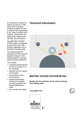
In printing and coating processes as well as in roller inking units of printing presses so-called ink mist or particle mist is generated in the outlet of double roller systems, coming from the appropriate coating material resp. the printing ink. The MISTING TACKER MTS20 system is designed to reduce ink mist in the printing / application nip of printing and coating units. The patented dual DC plasma bar R170A3 imparts separate charges to the particle streams, ensuring optimal particle separation. The benefits: • complete particle deposit on the roll surface or on the substrate • reduced ink and coating consumption • less pollution of the environement • optimal print/coating results at the highest processing speeds and lowest maintenance costs • less maintenance effort Technical Information MISTING TACKER SYSTEM MTS20 System for the reduction of ink mist in printing and coating units
Open the catalog to page 1
System Description MISTING TACKER SYSTEM MTS20 by Eltex In the application units of coating systems and in the inking units of printing presses, the ink or coating is split, distributed and transported by a series of roller pairs. The printing/coating substrate is transported in the nip between the application roller and the impression roller. At increasing processing speeds, the ink/coating is split into more than two parts, leading to free particles. The particle streams formed in the outlet have a wide particle size range; their diameter ranges from a few nanometers to a few micrometers depending...
Open the catalog to page 2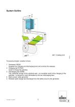
AW 1 Funcional principle / position of bars 1 Generator HSG61 Supplies the charging and discharging bars and controls the releases. 2 Charging bar R170A3 Used to charge the particles. 3 Discharging bar EXR50 The undesired charge of the substrate web - an inevitable result of the charging of the particles - is reduced or even eliminated by the two discharging bars. 4 Mains power cable generator 5 Release cable charge and discharge from the safety circuit to the generator
Open the catalog to page 3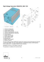
High Voltage Generator HSG61EX_S09 / S10 Terminal, charging bar Socket analog interface Socket CAN bus female Terminal, discharging bar inlet side Terminal, discharging bar outlet side Ground terminal Socket CAN bus male Socket supply voltage Fuse, primary circuit Discharge fuse Master switch ON/OFF Operator interface The high voltage generator HSG61EX supplies the charging and the discharging bars with the required high voltage. The high voltage generator is programmed directly via the keyboard. Once programmed, a reprogramming will not be necessary. Messages are shown on the display in plain...
Open the catalog to page 4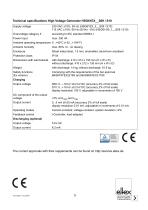
Technical specifications High Voltage Generator HSG61EX_S09 / S10 Supply voltage Overvoltage category II Power input Ambient operating temperature Ambient humidity Enclosure Protection class Dimensions with wall bracket Weight Safety functions (Ex version) Charging Output voltage AC component of the output voltage Output current Operating modes Feedback control Discharging (optional) Output voltage Output current 230 VAC ±10%, 50 Hz (HSG61EX_2__S09 / S10) 115 VAC ±10%, 60 Hz (50 Hz: -5%) (HSG61/00_1__S09 / S10) according to IEC standard 60664-1 max. 300 VA 0...+40°C (+32...+104°F) max. 80% r.h.,...
Open the catalog to page 5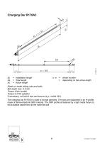
EL = Installation length n, m = whole number GL = Total length = depending on the active length AL = Active length Plastic or metal sliding nuts and bolts Bolt depth max. 6.5 mm Torque 4 Nm (metal) Torque 0.4 Nm (plastic) If necessary, cut bolt to size and secure (e.g. Loctite 243) The charging bar R170A3 is used to charge particles. The bars are supported in an H-profile made of flame-retardant GRP material. The GRP profile is fastened by a light metal fixture to the available attachment at the machine wall.
Open the catalog to page 6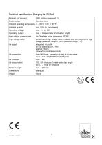
Technical specifications Charging Bar R170A3 Material, bar element Emission tips Ambient operating temperature Ambient humidity Operating voltage Operating current High voltage power supply HIgh voltage cable Air supply Air connection Air pressure Air consumption Bar total length Dimensions Weight GRP, casting compound PU Stainless steel 0...+60°C (+32...+140°F) max. 60% r.h., non-dewing max. ±19 kV DC max. 3 mA per meter of active bar length via Eltex high voltae generators HSG61 prefabricated high voltage cable in plastic tube with plug for the high voltage generator, length 1...99 m (standard...
Open the catalog to page 7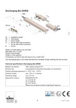
EL = Installation length GL = Total length AL = Active length A =95 mm with axial connection = 34 mm with radial connection B =40 mm Plastic or metall sliding nuts and bolts Bolt depth max. 6.5 mm Torque 4 Nm (metall) Torque 0.4 Nm (plastic) If necessary, cut bolt to size and secure (e.g. Loctite 243) Two discharging bars in the outlet eliminate the inevitable charge resulting from the process. Technical specifications Discharging Bar EXR50 Material, bar element GRP, casting compound PU Emission tips encapsulated and electrically decoupled, low capacitance Ambient operating temperature 0...+40°C...
Open the catalog to page 8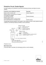
Protective Circuit, Enable Signals For each coating unit a protective circuit with the following functions (see figure) must be realized. To guarantee the safe operation of the system in the coating unit even under explosion-hazard conditions, the following enabling conditions must be observed. Release Discharge — Washing unit active — Web feed active Coating unit engaged — Minimum speed v >0 Release Charge — Web break Emerging stop — Impression cylinder in working position Minimum speed v >0.4 m/s 1,2,3,4: Input analogue interface Power supply ON when master switch of machine ON Housing permanently...
Open the catalog to page 9
Impression Cylinder Contact High voltage should not be enabled before a safe electrical contact is made between impression cylinder and transfer roller! For the lift-off of the impression cylinder the protective circuit must be designed such that the enabling mechanism of the high voltage is switched off before the impression cylinder lifts off, i.e. before there is no longer any contact with the substrat and the transfer roller This can be implemented by one of the following methods: • use of hydraulic or pneumatic pressure switches which respond to the increase in pressure (back pressure) after...
Open the catalog to page 10All Eltex-Elektrostatik-GmbH catalogs and technical brochures
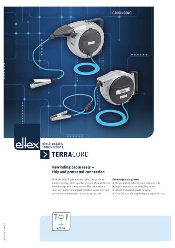 Brochure Cable reels
2 Pages
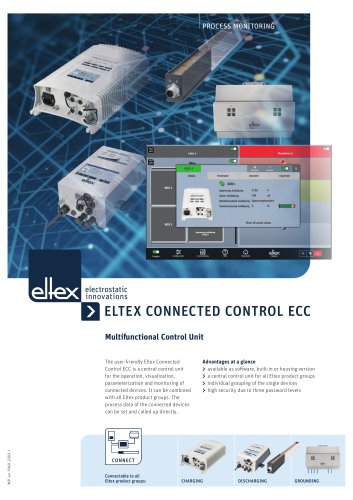 ELTEX CONNECTED CONTROL ECC
3 Pages
 Technical information GNH63
56 Pages
 Brochure ESA
15 Pages
 Operating Manual TERRALIGHT
36 Pages
 Brochure TERRALIGHT
3 Pages
 Brochure Power Charger
5 Pages
 POWER IONIZER - power supply
8 Pages
 Technical information SDS
4 Pages
 Brochure SDS
4 Pages
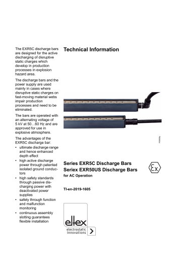 Technical information EXR5C
2 Pages
 Technical information R45
2 Pages
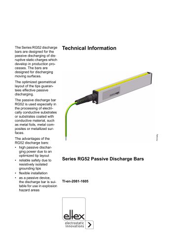 Technical information RG52
4 Pages
 Brochure flexION
4 Pages
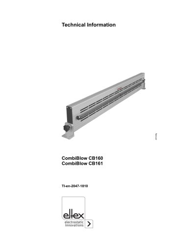 Technical information CB
4 Pages
 Brochure STATICJET RX22
3 Pages
 Technical information RX3
4 Pages
 Brochure RX3
3 Pages
 Technical information ES24
4 Pages
 Technical information WM3000
12 Pages
 Brochure WM3000
15 Pages
 Technical information SCC
3 Pages
 Brochure Discharging
7 Pages
 Brochure SCC
3 Pages
 Technical information DM1500
8 Pages
 Brochure DM1500
2 Pages
 Brochure RX11
3 Pages
 Technical information R23ATR
8 Pages
 Brochure MTS
3 Pages
 Brochure Grounding General
4 Pages
 Technical information PGT120
4 Pages
 Technical information GHH36
20 Pages
 Brochure GHH36
2 Pages
 Technical information ES53
4 Pages
 Technical information ES51
4 Pages
 Technical information R36
8 Pages
 Brochure Terrapharm General
2 Pages
 Brochure Terracap General
2 Pages
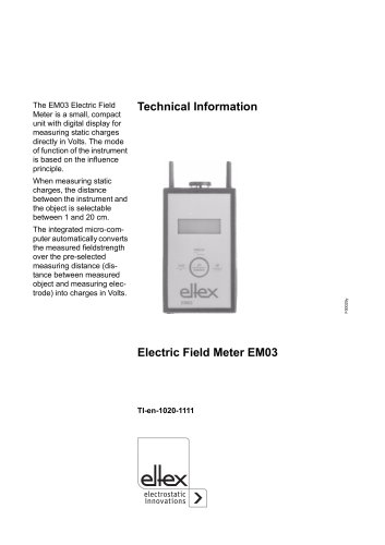 Technical information EM03
2 Pages
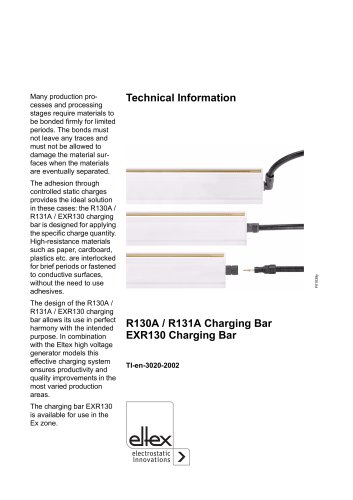
 Brochure Charging bars
5 Pages
 Brochure Ground clamps
4 Pages


Archived catalogs
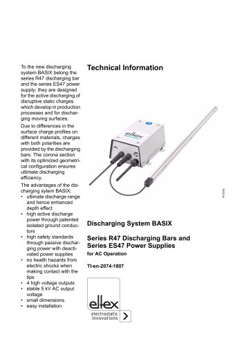
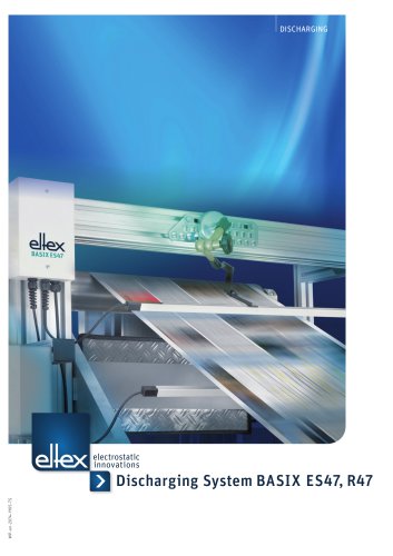 Brochure BASIX ES47,R47
4 Pages
 Technical information R55
8 Pages
 Brochure Ion Blower
5 Pages

- DC power supply
- AC/DC power supply
- Electrical cable
- Touch screen display panel
- Tabletop power supply
- Compact power supply
- Control display system
- Cleaning nozzle
- Air nozzle
- High-voltage power supply
- Air gun
- Stabilized power supply
- Rewinder-winder
- Blow-off nozzle
- Cleaning air blow gun
- Anti-static bar
- Nozzle air blow gun