
- Catalogs
- Eltex-Elektrostatik-GmbH
- Technical information GNH63

Technical information GNH63

Technical information GNH63
- Function: The Electrostatic Printing Assist (ESA) system enhances gravure printing by using electrical fields to improve ink transfer, reducing missing dots and improving print quality.
- Printing Quality: Ensures no missing dots by maintaining clean system components, proper roller coating, and suitable material resistance. Ink conductivity and drying are critical for quality.
- System Structure: Describes the maximum configuration of the ESA system, including optional components marked with a symbol.
- Risks and Hazards: The system is designed to be safe but improper use can lead to hazards. Safety instructions must be followed.
- Includes detailed instructions on assembling and installing various components like impression roller electrodes and high voltage generators.
- Startup and Modes: Describes startup procedures and different operating modes, including direct operation via the generator and control room integration.
- Regular maintenance of generators and electrodes is necessary to ensure system efficiency and safety.
- Provides warranty details and troubleshooting steps for common error messages related to the visualization system and generator.
- Lists available spare parts and accessories for the system.
- Includes technical specifications and measurement regulations for impression rollers, pollution monitoring, and other detailed technical data.
The document uses specific symbols to indicate warnings and cautions. A 'Warning!' symbol indicates operations that could cause serious injuries if not performed correctly. A 'Caution!' symbol warns of potential property damage. An 'Ex Warning!' is specific to units with EX approval, highlighting special conditions for explosion hazard areas.
Installation sites are outside Eltex's control, and contact protection against accidental contact with electrodes and live components may be required. Conductive contact protection devices must be grounded.
Regular inspections of protective resistors are necessary, with intervals specified by accident prevention regulations. Separate instructions are provided for specific electrodes.
The manufacturer may update technical specifications without notice to align with engineering advancements. Updated information is available upon request.
The ESA GNH63 system is designed for non-contact electrostatic printing assist on gravure printing machines. It must be used with specific electrodes and generators, adhering to voltage limits and operational conditions. Unauthorized modifications or improper use void warranties and liabilities.
Safety instructions must be followed precisely. Electrical equipment regulations must be observed. Power supply disconnection is required before installation, maintenance, or troubleshooting. Only qualified electricians should perform work on the devices. Specific conditions apply when using conductive inks or substrates, and the generator must be operated by trained personnel. Proper grounding and protective circuits are essential for safe operation.
Regular checks and maintenance are crucial for safe operation. This includes ensuring clean electrodes, proper grounding, and adherence to installation distances to prevent sparking and equipment damage. The document outlines specific procedures for handling high voltage cables, cleaning electrodes, and ensuring the functionality of protective circuits.
The operation of electrodes can generate ozone, and its concentration depends on various factors. The maximum allowable concentration must be monitored to ensure workplace safety.
The document outlines international limits for electrostatic charges and emphasizes the importance of wearing conductive footwear when working near electrodes. It references national regulations like TRGS 727 in Germany for avoiding ignition hazards due to electrostatic charges.
Protective Circuit and Enable Signals: The protective circuit ensures safe operation under explosion-hazard conditions. Key conditions include disabling discharging functions when the web infeed is active and ensuring no solvent covers the electrodes during the impression roller washing process. The high voltage should only be enabled when a safe electrical contact is made between the impression roller and cylinder.
The impression roller must be free of conductive materials to prevent sparking. Minimum distances for various components are specified, such as a 10 mm minimum distance for limit switches and splash proofing.
Electrodes should be attached using flame-retarding GRP materials. Specific distances must be maintained to prevent leakage currents, such as a 40 mm clearance from conductive materials and a creepage distance of over 150 mm.
The active length of the electrode should be calculated based on the impression roller's specifications. The document provides a formula for determining the active length and emphasizes that the electrode's total length should not exceed the paper web width.
The discharging electrode should be installed using GRP round bars and plastic holders. Specific installation distances are required to prevent damage, such as a 200 mm free air routing for high voltage cables and a 30-100 mm distance between the electrode and paper.
The discharging electrode should be positioned to maintain a distance of 30-100 mm from the material web surface. The document advises adhering to recommended distances to avoid polarity changes during high web speeds.
Error messages related to soiled electrodes and generator issues are displayed on the visualization system. Maintenance or repair work should only be performed by qualified electricians after deactivating the generator and disconnecting the supply voltage.
- Missing Dots: Caused by dirty electrodes or unsuitable conditions. Remedy includes cleaning electrodes and adapting operating conditions.
- Generator Cannot Be Switched On: Due to a defective fuse or disconnected supply voltage. Remedy involves replacing the fuse and connecting the supply voltage.
- Decrease in Efficiency: Caused by polluted or defective charging electrodes. Remedy includes cleaning electrodes and replacing defective parts.
A list of spare parts and accessories is provided, including high voltage generators, impression roller electrodes, and various cables. Each item has a reference code for ordering.
For proper function of the ESA Electrostatic Printing Assist, impression rollers must meet specific electrical resistance values. These include insulation resistance (Ri), total volume resistance (Rvt), and conductor resistance (RL).
Guidelines for measuring resistance values in 2-layer and 3-layer impression rollers are provided. Measurements should be taken at operating temperature using specified equipment.
Pollution monitoring is available for impression roller electrodes in certain generator variants. It involves comparing nominal and load resistance values to determine pollution levels. A warning is issued if pollution exceeds 80%, and an error message is triggered if it exceeds 100%.
Catalog excerpts

Operating Instructions POWER TOP Electrostatic Printing Assist Series GNH63
Open the catalog to page 1
System description . . . . . . . . . . . . . . . . . . . . . . . . . . . . . . . . . . . . 6 Function . . . . . . . . . . . . . . . . . . . . . . . . . . . . . . . . . . . . . . . . . . . . . . 6 Printing quality . . . . . . . . . . . . . . . . . . . . . . . . . . . . . . . . . . . . . . . . . 8 System structure . . . . . . . . . . . . . . . . . . . . . . . . . . . . . . . . . . . . . . . 9 System components . . . . . . . . . . . . . . . . . . . . . . . . . . . . . . . . . . . 10 Safety . . . . . . . . . . . . . . . . . . . . . . . . . . . . . . . . . . . . . . . . . . . . . . 12 Identification...
Open the catalog to page 3
Maintenance . . . . . . . . . . . . . . . . . . . . . . . . . . . . . . . . . . . . . . . . .39 Generator . . . . . . . . . . . . . . . . . . . . . . . . . . . . . . . . . . . . . . . . . . . .39 Electrodes . . . . . . . . . . . . . . . . . . . . . . . . . . . . . . . . . . . . . . . . . . . .39 Inspection of the protective resistors - contact protection . . . . . . . .40 Visualization system Eltex Connected Control ECC # . . . . . . . . . .41 7 Trouble-shooting . . . . . . . . . . . . . . . . . . . . . . . . . . . . . . . . . . . . .43 7.1 Error messages Visualization system Eltex Connected...
Open the catalog to page 4
Dear customer, The main function of the electrostatic printing assist ESA in gravure printing is to support the discharge of the ink-filled cells to avoid missing dots. Also, the discharging performance of the cells is improved overall. This means that the printing density can be controlled to a certain extent. The ESA system monitors the charge conditions in the printing units in which this system is installed. The benefits: • Improved printing quality (no missing dots) • Less wear on the impression rollers by reducing the mechanical contact force • Suitable for use in the EX zone in the gas...
Open the catalog to page 5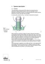
1. System description 1.1 Function The electrostatic printing assist ESA utilises the physical fact that electrically charged particles (gravure inks are composed of such particles) are exposed to forces in an electrical field which always shift the particles into areas with higher field strengths. A simple plate condenser (Fig. 1) will help to illustrate this situation. When applying an electrical voltage, the plate condenser generates a homogeneous electrical field between the plates which has a much lower field strength at the edges and outside the plates than between the actual plates. If...
Open the catalog to page 6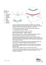
Printing unit Dielectric insulator Impression roller Paper Printing cylinder Filled cell In gravure printing the electrical field is generated in the printing nip between impression roller and impression cylinder. Both the substrate to be printed and the ink are dielectric materials, i.e. insulators. To achieve the desired effect, electrical field strengths of between 3...5 megavolt per meter are required. The electrical field strength is defined as follows: electrical field strength = voltage / distance With a distance of 0.1 mm, which is roughly the thickness of gravure paper, the voltage required...
Open the catalog to page 7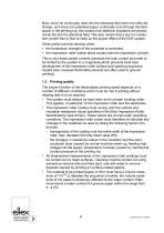
Now, since ink continually rises into the electrical field when the cells discharge, and since non-polarised paper continually runs through the field space in the printing nip, this means that dielectric insulators are permanently fed into the electrical field. This also means that a low but consistent current has to flow to keep up the proper effect of the ESA system. Other partial currents develop when: • the breakdown strength of the substrate is exceeded, • the impression roller makes direct contact with the impression cylinder. This is why these partial currents dominate the total current...
Open the catalog to page 8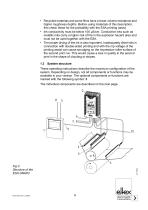
• Recycled materials and some films have a lower volume resistance and higher roughness depths. Before using materials of this description, first check these for the printability with the ESA printing assist. • Ink conductivity must be below 100 µS/cm. Conductive inks such as metallic inks carry a higher risk of fire in the explosion hazard area and must not be used together with the ESA. • The proper drying of the ink is also important. Inadequately dried inks in connection with double-sided printing and with the nip voltage of the printing assist can cause smudging on the impression roller...
Open the catalog to page 9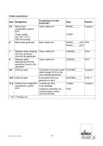
Cable connections
Open the catalog to page 11
2. Safety The units have been designed, built and tested using state-of-the-art engineering, and have left the factory in a technically and operationally safe condition. If used improperly, the units may nevertheless be hazardous to personnel and may cause injury or damage. Read the operating instructions carefully and observe the safety instructions. 2.1 Identification of risks and hazards Possible risks and hazards resulting from the use of the units are referred to in these operating instructions by the following symbols: Warning! This symbol appearing in the operating instructions refers...
Open the catalog to page 12
2.4 Technical advance The manufacturer reserves the right to make changes to the technical specifications without prior notice in order to adapt the units to state-ofthe-art engineering. Eltex will provide the latest information on any changes or modifications in the operating instructions on request. 2.5 Proper Use The system ESA GNH63 must only be used for the non-contacting electrostatic printing assist on gravure printing machines. Impression roller electrodes and discharging electrodes are approved solely for use and operation with PCTL/_ _ generator. This ensures that: • the maximum permissible...
Open the catalog to page 13
• If electrically conductive ink is used to print in a printing unit fitted with ESA, the ESA charging voltage must be disabled in this printing unit and in all following printing units. Discharging must also be switched off resp. moved to the "passive" operating mode (optional). If the passive operating mode is not available, the mains voltage of the generator must also be switched off. • If electrically conductive substrates or substrates coated with conductive material (e.g. metal foil or metal composites) are used in the printing process, the ESA charging voltage must be disabled in these...
Open the catalog to page 14All Eltex-Elektrostatik-GmbH catalogs and technical brochures
 Brochure Cable reels
2 Pages
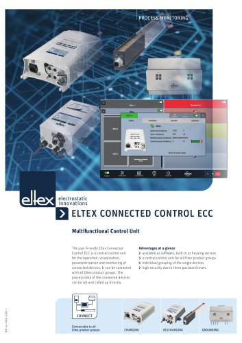 ELTEX CONNECTED CONTROL ECC
3 Pages
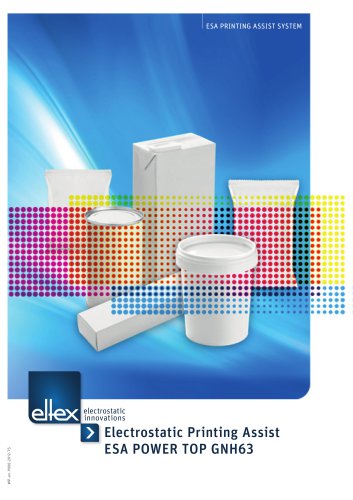 Brochure ESA
15 Pages
 Operating Manual TERRALIGHT
36 Pages
 Brochure TERRALIGHT
3 Pages
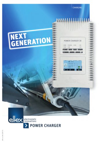 Brochure Power Charger
5 Pages
 POWER IONIZER - power supply
8 Pages
 Technical information SDS
4 Pages
 Brochure SDS
4 Pages
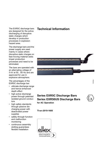 Technical information EXR5C
2 Pages
 Technical information R45
2 Pages
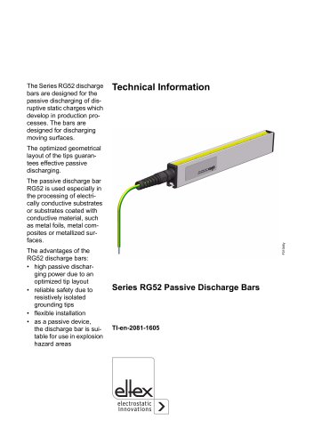 Technical information RG52
4 Pages
 Brochure flexION
4 Pages
 Technical information CB
4 Pages
 Brochure STATICJET RX22
3 Pages
 Technical information RX3
4 Pages
 Brochure RX3
3 Pages
 Technical information ES24
4 Pages
 Technical information WM3000
12 Pages
 Brochure WM3000
15 Pages
 Technical information SCC
3 Pages
 Brochure Discharging
7 Pages
 Brochure SCC
3 Pages
 Technical information DM1500
8 Pages
 Brochure DM1500
2 Pages
 Brochure RX11
3 Pages
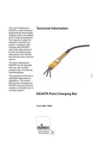 Technical information R23ATR
8 Pages
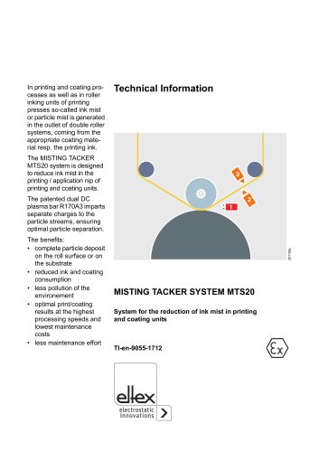 Technical information MTS
12 Pages
 Brochure MTS
3 Pages
 Brochure Grounding General
4 Pages
 Technical information PGT120
4 Pages
 Technical information GHH36
20 Pages
 Brochure GHH36
2 Pages
 Technical information ES53
4 Pages
 Technical information ES51
4 Pages
 Technical information R36
8 Pages
 Brochure Terrapharm General
2 Pages
 Brochure Terracap General
2 Pages
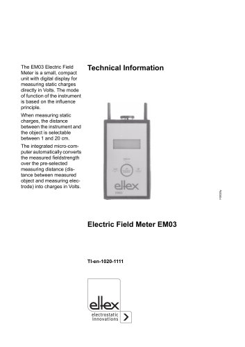 Technical information EM03
2 Pages
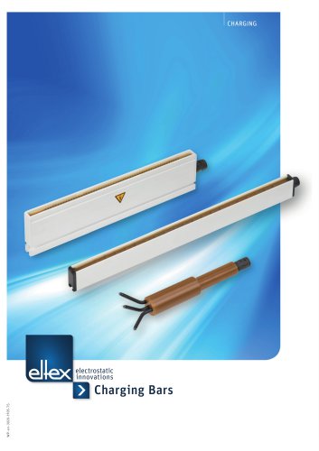 Brochure Charging bars
5 Pages
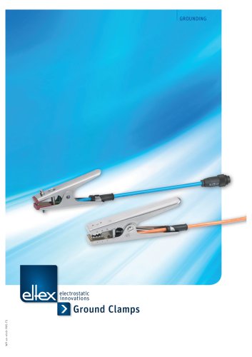 Brochure Ground clamps
4 Pages







Archived catalogs
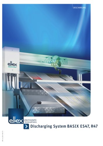 Brochure BASIX ES47,R47
4 Pages
 Technical information R55
8 Pages
 Brochure Ion Blower
5 Pages

- DC power supply
- Electrical cable
- AC/DC power supply
- Power cable
- Touch screen display panel
- Compact power supply
- Control display system
- Tabletop power supply
- Cleaning nozzle
- Air nozzle
- High-voltage power supply
- Air gun
- Stabilized power supply
- Rewinder-winder
- Blow-off nozzle
- Antistatic bar
- Cleaning air blow gun
- Hermetic electrical cable