- Catalogs
- Eltex-Elektrostatik-GmbH
- Operating Manual TERRALIGHT
Operating Manual TERRALIGHT
1 /36Pages

Operating Manual TERRALIGHT
1 /36Pages
Catalog excerpts

Operating Instructions Ground Monitoring System TERRALIGHT
Open the catalog to page 1
Overview of Appliance TERRALIGHT Ground Monitoring System . . . . . . . . . . . . . . . . . 5 1.1 Components . . . . . . . . . . . . . . . . . . . . . . . . . . . . . . . . . . . . . . . . . . . 6 1.2 Variants . . . . . . . . . . . . . . . . . . . . . . . . . . . . . . . . . . . . . . . . . . . . . . 6 2 Safety . . . . . . . . . . . . . . . . . . . . . . . . . . . . . . . . . . . . . . . . . . . . . . . 7 2.1 Identification of risks and hazards . . . . . . . . . . . . . . . . . . . . . . . . . . 7 2.2 Technical advance . . . . . . . . . . . . . . . . . . . . . . . . . . . . . . . . . . . . ....
Open the catalog to page 3
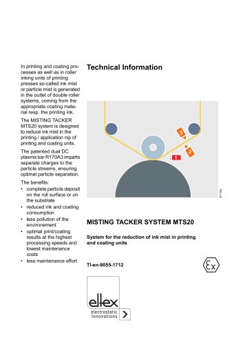
Dear customer, The controlled grounding principle used in the TERRALIGHT Ground Monitoring System ensures that static charges developing in potentially explosive atmospheres, e.g. during loading, discharging or refilling are safely avoided. This means that the risk of ignition caused by uncontrolled static discharges is eliminated at source. Because the ground connection is monitored, there is no need for low-resistance ground connections or large conductor cross-sectionsStatic charges are caused by the contact and separation of material surfaces, e.g. when pumping liquid or powdery materials...
Open the catalog to page 4
1. Overview of Appliance TERRALIGHT Ground Monitoring System Ground contactors and cables Monitoring system Overview TERRALIGHT Ground Monitoring System 1 TERRALIGHT 2 Cable rewinder, aluminum, 601KR/AW and 601KR/DW with ground clamp 3 Cable rewinder, plastic, 601KR/KW with ground clamp 4 Ground clamp 5 Ground cable KG/BNA 6 Helix ground cable KG/BSA 7 Light plug 8 Clamp holder (optional in 2 versions, available as an accessory
Open the catalog to page 5
1.1 Components TERRALIGHT for installation in explosion hazard areas operating voltage 3 x 1.5 V DC (batteries) for connecting one ground contactor Light plug display of the connection to ground LED adapter cable coupling 601KR/AW, 601KR/DW, 601KR/KW cable rewinder Series 70 ground clamps see separate Operating Instructions BA-en-4007 TERRACLAMP ground clamps see separate Operating Instructions BA-en-4014 1.2 Variants Power supply B = Battery Cable gland B = Brass S = Stainless steel Variant 000 = Standard version
Open the catalog to page 6
2. Safety The units have been designed, built and tested using state-of-the-art engineering, and have left the factory in a technically and operationally safe condition. If used improperly, the units may nevertheless be hazardous to personnel and may cause injury or damage. Read the operating instructions carefully and observe the safety instructions. 2.1 Identification of risks and hazards Possible risks and hazards resulting from the use of the units are referred to in these operating instructions by the following symbols: Warning! This symbol appearing in the operating instructions refers...
Open the catalog to page 7
2.4 Work and operational safety Warning!electricians Carefully observe the following notes and the complete Chapter 2 "Safety”, page 7! • The local standards, rules and regulations relating to the installation and operation of electrical appliances in potentially explosive atmospheres must be observed (e.g. EN 60079-14 and EN 60079-17 in the EU and ElexV in Germany). • Appliances designed for use in potentially explosive atmospheres must not be modified. The technical specifications for ambient conditions and operation must be maintained and observed (see Chapter 8 "Technical specifications”,...
Open the catalog to page 8
• The maximum cable length in the intrinsically safe circuit must not exceed the maximum permissible capacity and inductance (see Chapter 8 "Technical specifications”, page 27). • The ground monitoring system must always be connected to the equipotential bonding conductor (see Chapter 3.4.1 "Cable connection”, page 15). • If the ground cable is subjected to tensile stress in the application (e.g. if KG/BN_ (ground cable) or KG/BS_(helix ground cable) is used), the cable must be secured additionally with an external strain relief (e.g. a strap clip); see Chapter 3.4.1 "Cable connection”, page...
Open the catalog to page 9
2.5 Special conditions according to the declaration of conformity • Only the following battery types (D cells) may be used to operate the TERRALIGHT system: - Duracell Plus Power MN 1300 - ENERGIZER MAX LR20 - ENERGIZER LR20 ALKALINE POWER (see Chapter 3.4.2 "Changing batteries (Fig. 6)”, page 16). • The batteries may only be replaced if it can be ensured that a potentially explosive atmosphere does not exist at this instant of time (see Chapter 3.4.2 "Changing batteries (Fig. 6)”, page 16). • Equipotential bonding (PA) shall be established along the entire cable run of the measuring circuit...
Open the catalog to page 10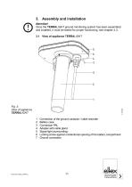
3. Assembly and installation Attention! Once the TERRALIGHT ground monitoring system has been assembled and installed, it must be tested for proper functioning, see chapter 4.3. 3.1 View of appliance TERRALIGHT Connection of the ground contactor / cable rewinder Battery case Connection PAL Adapter with cable gland Signal light (surrounding) Locking screw against unintentional opening of the battery compartment Ground connection
Open the catalog to page 11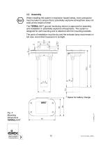
When installing the system in explosion hazard areas, every precaution must be taken to ensure that a potentially explosive atmosphere does not exist at this instant of time! The TERRALIGHT ground monitoring device is approved for assembly and installation in potentially explosive atmospheres. The system is designed for wall mounting and is attached with the mounting brackets. The point of installation must be dry and the indicator lamp must remain in full view. Avoid direct exposure to sunlight. Fig. 4: Mounting Dimensions TERRALIGHT * Space for battery change
Open the catalog to page 12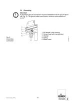
M4 thread in the housing Ground lead with ring terminal Washer Spring M4x6 screw Attention! A permanent ground connection must be established via the ground terminal (Fig. 5). The ground cable must have a minimum cross-section of 4 mm².
Open the catalog to page 13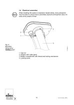
When installing the system in explosion hazard areas, every precaution must be taken to ensure that a potentially explosive atmosphere does not exist at this instant of time! Fig. 6: Mounting Dimensions TERRALIGHT 1. Cap nut 2. Adapter with cable gland 3. Battery compartment with thread and locking mechanism 4. Locking screw
Open the catalog to page 14All Eltex-Elektrostatik-GmbH catalogs and technical brochures
 Brochure Cable reels
2 Pages
 ELTEX CONNECTED CONTROL ECC
3 Pages
 Technical information GNH63
56 Pages
 Brochure ESA
15 Pages
 Brochure TERRALIGHT
3 Pages
 Brochure Power Charger
5 Pages
 POWER IONIZER - power supply
8 Pages
 Technical information SDS
4 Pages
 Brochure SDS
4 Pages
 Technical information EXR5C
2 Pages
 Technical information R45
2 Pages
 Technical information RG52
4 Pages
 Brochure flexION
4 Pages
 Technical information CB
4 Pages
 Brochure STATICJET RX22
3 Pages
 Technical information RX3
4 Pages
 Brochure RX3
3 Pages
 Technical information ES24
4 Pages
 Technical information WM3000
12 Pages
 Brochure WM3000
15 Pages
 Technical information SCC
3 Pages
 Brochure Discharging
7 Pages
 Brochure SCC
3 Pages
 Technical information DM1500
8 Pages
 Brochure DM1500
2 Pages
 Brochure RX11
3 Pages
 Technical information R23ATR
8 Pages
 Technical information MTS
12 Pages
 Brochure MTS
3 Pages
 Brochure Grounding General
4 Pages
 Technical information PGT120
4 Pages
 Technical information GHH36
20 Pages
 Brochure GHH36
2 Pages
 Technical information ES53
4 Pages
 Technical information ES51
4 Pages
 Technical information R36
8 Pages
 Brochure Terrapharm General
2 Pages
 Brochure Terracap General
2 Pages
 Technical information EM03
2 Pages
 Brochure Charging bars
5 Pages
 Brochure Ground clamps
4 Pages


Archived catalogs
 Brochure BASIX ES47,R47
4 Pages
 Technical information R55
8 Pages
 Brochure Ion Blower
5 Pages

- DC power supply
- AC/DC power supply
- Electrical cable
- Power cable
- Touch screen display panel
- Tabletop power supply
- Compact power supply
- Control display system
- Cleaning nozzle
- Air nozzle
- High-voltage power supply
- Air gun
- Stabilized power supply
- Rewinder-winder
- Blow-off nozzle
- Cleaning air blow gun
- Anti-static bar
- Nozzle air blow gun