EKA
1 /16Pages

EKA
1 /16Pages
Catalog excerpts

ELECTRICAL CIRCULAR DUCT HEATERS Technical data Moun ng Maintenance
Open the catalog to page 1
Thank you for your purchase of this product. This manual describes how to use and install the supplied product. Be sure that you have read and understood its contents before using the heater. The electrical heater's model and serial number are located on the label of the product. WARNING! SAFETY REQUIREMENTS Improper use of this heater can result in serious bodily injury due to hazards of fire and explosion, burn and electrical shock. Use only with electrical voltage and frequency specified on model label. Do not perform any service with heater plugged in. Serious injury or death may occur if personnel...
Open the catalog to page 2
Table of contents Description 4
Open the catalog to page 3
Descrip on Electrical duct heaters EKA are designed to heat fresh air in ven la on systems. Casing (EKA protec on class IP 44, except EKA Type NV which protec on class IP 30) is made from Aluzinc coated steel which is high temperature proof and with rubber seals for duct connec on. Tube of hea ng element is made from stainless steel AISI 304. There are 2 protec on thermostats and screw terminals for easy connec on installed in the heaters. Heaters can be installed horizontally with the electrical connec on box facing upwards or sideways and ver cally (only if the air flow direc on upwards). Heaters...
Open the catalog to page 4
Installa on and electrical connec on Electrical duct heaters EKA can be installed horizontally in any posi on except electrical connec on box downward and ver cally (only if the air flow direc on upwards) (see Fig. 2). IMPORTANT: The installa on to the mains power supply may only be wired by a competent electrician. The power supply cable must be selected in the ra o with power of the heater. When installing these heaters, the standards and regula ons in force in your country must be followed strictly adhered to. Within the installa on an electrical isola on automa c circuit breaker (not included)...
Open the catalog to page 5
Fig. 4. Moun ng example EKA NIS/ESKM… *- External control signal (0…10VDC) is used in EKA NIS type heater. **- External PWM control signal ON/OFF: ON (6…24VDC) is used in EKA ESKM type heater. Fig. 5. Moun ng example EKA NV/NI…2NTC… *- Temperature set point knob and TR NTC10 are used in EKA NV 2NTC heater version. **- TR5K NTC10 is used in EKA NI 2NTC heater version. Fig. 6. Moun ng example EKA NV/NI… (Preheater) **- TR5K used only in EKA NI pre-heater version. *- Temperature set point knob used only in EKA NV pre-heater version.
Open the catalog to page 6
Fig. 7. Moun ng example EKA NIS/ESKM… (Preheater) *- External control signal 0…10VDC (from AHU if possible) is used in EKA NIS type pre-heater. **- External PWM control signal ON/OFF: ON 6…24VDC (from AHU if possible) is used in EKA ESKM type preheater. Type 1 – Standard EKA heater dimensions; Type 2 – EKA heater with external pressure relay dimensions; Type 3 – EKA heater with external cooling radiator dimensions; Type 4 – EKA heater with external cooling radiator and pressure relay di
Open the catalog to page 7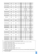
This declaration is in conformity with the requirements of the standards: LST EN 60335-2-30:2010+AC:2010+A11:2012+AC:2015 (EN60335-2-30:2009+ AC:2010+ A11:2012+ +AC:2014); LST EN61000-4-2:2009 (EN61000-4-2:2009); LST EN 61000-4-3:2006+A1:2008+A2:2010 (EN 61000-4-3:2006+A1:2008+A2:2010); LST EN 61000-4-4:2013 (EN 61000-4-4:2012); LST EN 61000-4-5:2014 (EN 61000-4-5:2014); LST EN 61000-4-11:2004 (EN 61000-4-11:2004); LST EN 61000-6-2:2005 (EN 61000-6-2:2005); LST EN 61000-3-2:2014 (EN 61000-3-2:2014); LST EN 61000-6-3:2007 + A1:2011 (EN 61000-6-3:2007 + A1:2011); LST EN 61000-3-3:2014 (EN 61000-3-3:2013)....
Open the catalog to page 9
without integrated control with integrated controller 1A- Control type: NV - Potentiometer for temperature control is on the lid of the heater NJ - External wired remote setpoint knob (TR5K) for temperature control NlS- External wired remote (0...10) VDCsignal for temperature control (analog input) ESKM|- External wired remote PWM (ON/OFF: ON (6.24) VDC) signal for temperature control 2 - Heating power (kW) 0.3 -0,3 kW ... 240- 24,0 kW (NV, NI, NIS) >15 kW with mounted additional step 03- 0,3 kW ... 15a- 15,0 kW (ESKM) - Differential pressure switch for air flow detection _-Sensor for minimum...
Open the catalog to page 10
Two overheat protection thermostats are installed in the electrical circular heater EKA. The first one with automatic reset, turns off the heating when the temperature reaches 50 °C and turns on when the temperature drops below 50 °C. The second with manual reset, turns off the heating when the temperature reaches 100 °C. In this case need to figure the cause of the overheating of the heater. Eliminate overheating cause, press „RESET" button on heaters cover. Additional overheating thermostat (with automatic reset) is installed in the EKA heater with ESKM to protect the ESKM controller. This...
Open the catalog to page 11
Descrip on of opera ng EKA NIS … Electrical duct heaters EKA NIS … are designed for the heaters power (0…100) % control by analog signal input (0…10) VDC. When the heater power supply is switched on, LED 6 on the controller (EKR-K…) PCB (see Fig. 1 on page 4) flashes every second. If controller turns on the hea ng depending on analog signal, LED 5 lights (see Fig. 1 on page 4). Descrip on of opera ng EKA NV … (PTC…PS) Electrical duct heaters EKA NV … (PTC…PS) are designed with integrated temperature control, PTC (air velocity), PS (air pressure) and temperature sensors, setpoint poten ometer knob...
Open the catalog to page 12
Descrip on of opera ng EKA NIS … (PTC…PS) * Electrical duct heaters EKA NIS … (PTC…PS) are designed for the heaters power (0…100) % control by analog signal input (0…10) VDC, with integrated PTC (air velocity) and PS (air pressure) sensors. When the heater power supply is switched on, controller (EKR-K…) is in prepara on mode for 30 seconds, LED 1 flashes once every 5 seconds. If air velocity is detected by PTC sensor (rapid LED 1 flashes when Min. 1,5 m/s is detected) and air pressure is greater than min 20kPA a er prepara on mode ends, LED 1 will start to flash once every second and controller...
Open the catalog to page 13All ELTA FANS catalogs and technical brochures
 SPIGOT SILENCER
8 Pages
 SPLITTER SILENCER
4 Pages
 SQUARE FLEXIBLE CONNECTOR
4 Pages
 TWINFLOW STDL
14 Pages
 VERSALINE VL
8 Pages
 BACKDRAUGHT SHUTTERS
4 Pages
 ACH580-01/-31
7 Pages
 QUBE SQUHT
14 Pages
 EKS
EKS69 Pages
 SINGLEFLOW SSDL
14 Pages
 HIDEAWAY SH
10 Pages
 COMPACT SCD
12 Pages
 COMPACT SCP
20 Pages

