- Company
- Products
- Catalogs
- News & Trends
- Exhibitions
Reluctance Triggers EL-TRG_R
1 /4Pages

Reluctance Triggers EL-TRG_R
1 /4Pages
Catalog excerpts
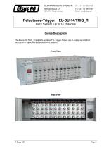
ELEKTRONISCHE SYSTEME Rack System, up to 14 channels Device Description The device EL-TRIG_R is able to produce TTL-Trigger-Pulses out of analog signals from reluctance or capacitive and eddy-current sensors. Front View Rear View
Open the catalog to page 1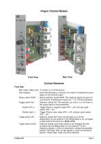
Plug-In Channel Module Front View Rear View Control Elements Front Side Main switch (Base Unit) :To switch on or off the device. LED-Displays : Each LED belongs to a channel, from which it indicates the pulse signal on the channel output. Rotary switch GAIN : Rotary switches named GAIN. This switches adjusts the gain for one channel. Possible gain factors are 1, 10, 100 and automatic. Toggle switch Pol. : Switches named Pol. This switches can invert (-) or not invert (+) the output signal of the preamplifier. Position left (+) : Trigger-Pulse on negative slope (Diff. = off), and neg. peak values...
Open the catalog to page 2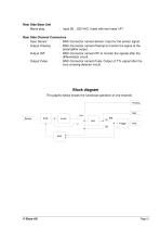
Rear Side Base Unit Mains plug : Input 95 .. 230 VAC, fused with two fuses 1AT Rear Side Channel Connectors Input Sensor : BNC-Connector named Sensor. Input for the sensor signal. Output Preamp. : BNC-Connector named Preamp to monitor the signal at the preamplifier output. Output Diff. : BNC-Connector named Diff to monitor the signals after the differentiator circuit. Output Pulse : BNC-Connector named Pulse. Output of TTL-signal after the zero crossing detector circuit. Block diagram The graphic below shows the functional operation of one channel. P re a m p .
Open the catalog to page 3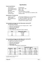
Specifications Channel specifications: Input sensitivity Input impedance Diff on Input impedance Diff off Bandwidth Max. input voltage Pulse output All other outputs See table below approx. 102kΩ || 10pF approx. 17kΩ 30 Hz to 30kHz ± 35V (short peaks up to 250V) TTL (0.4 ... 3.5 V), Pulse width 5µs, Impedance 100Ω Impedance 560Ω Specifications of the Base Unit: Number of channels Supply voltage Dim. of Rack Chassis Weight One per Plug-In Module (up to 14 in one chassis) 95 .. 230 VAC, fused with two fuses 1AT 19”, 480 x 134 x 260 mm (W x H x D) Rack chassis with 14 channels: 5.3 kg one plug-In...
Open the catalog to page 4All Elsys AG catalogs and technical brochures
 Low Noise Amplifier LNA-2
2 Pages
 EL-BULT14
3 Pages
 TraNET EPC Datasheet
9 Pages
 TraNET FE 408 DP
5 Pages
 EL-DAQ Data Logger Solution
3 Pages
 Elsys Product Overview
15 Pages


Archived catalogs

- Rectangular housing
- Data logger
- Process software
- Temperature datalogger
- Measurement software
- Generator
- Signal amplifying integrated circuit
- Protection housing
- Electronic equipment enclosure
- Programming software
- Datalogger without display
- IP65 housing
- Monitoring datalogger
- Programmable datalogger
- Data acquisition unit
- Data acquisition software
- Pressure logger
- CAM software
- Measuring amplifier
- Multi-channel datalogger