- Company
- Products
- Catalogs
- News & Trends
- Exhibitions
EL-BULT14
1 /3Pages

EL-BULT14
1 /3Pages
Catalog excerpts

The device EL-BULT14 is able to produce TTL trigger pulses out of analog signals from optical (Laser), reluctance, capacitive and eddy-current sensors. The main application of the EL-BULT14 is to convert sensor signals to TTL pulses in structural health monitoring and vibration measurements of compressors and turbine blades. The channel selectors can be used to route the amplified input signal as well as the trigger output pulse from one of the 14 channels to the front BNC connectors for monitoring purposes. Each of the up to 14 channels has a corresponding input (Probe In) and trigger pulse out (Pulse Out) BNC connector on the rear side of the device. Elsys AG Mellingerstrasse 12 CH-5443 Niederrohrdorf Switzerland Phone: +41 56 496 01 55 Email: [email protected] www.elsys-instruments.com
Open the catalog to page 1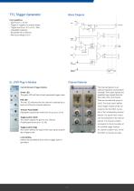
Block Diagram Key Capabilities • Gain factors 1, 10, 100 • Trigger on negative or positive slopes • Trigger level from (-9 to +9 V) / Gain • Adjustable hysteresis • Bandwidth DC to 400 kHz • Max input voltage ±42 V Back plane Ch-Selector Logic Channel Selector Control Elements Trigger-Module The Channel Selector is an optional module for accessing all installed LTM1 output signals and amplified input signals from the front-side of the rack chassis. Green LED The green LED will flash at each generated trigger pulse. Red LED The red LED indicates that this channel is selected by at least one of...
Open the catalog to page 2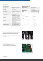
Channel Specifications Input Amplifier Specifications of the Base Unit Signals Adjusting of the Hysteresis The value of the hysteresis can be adjusted by a potentiometer, It is accessible by removing the top cover of the EL-BULT14 rack, Turning clockwise increases the hysteresis, The value of the hysteresis can be set between approx, 0,35 to 4,5 % of the amplifier range (e.g. 10 mV to 500 mV at gain=1). By installing the jumper J2, the hysteresis will be increased by a factor of approx, 3 (e.g 30 mV to 1,5 V at gain=1), This may be helpful at the use of reluctance sensors, © 2023 Elsys AG
Open the catalog to page 3All Elsys AG catalogs and technical brochures
 Low Noise Amplifier LNA-2
2 Pages
 TraNET EPC Datasheet
9 Pages
 TraNET FE 408 DP
5 Pages
 EL-DAQ Data Logger Solution
3 Pages
 Elsys Product Overview
15 Pages
 Reluctance Triggers EL-TRG_R
4 Pages


Archived catalogs

- Rectangular housing
- Data logger
- Process software
- Temperature datalogger
- Measurement software
- Generator
- Signal amplifying integrated circuit
- Protection housing
- Electronic equipment enclosure
- Programming software
- Datalogger without display
- IP65 housing
- Monitoring datalogger
- Programmable datalogger
- Data acquisition unit
- Data acquisition software
- Pressure logger
- CAM software
- Measuring amplifier
- Multi-channel datalogger