

- Company
- Products
- Catalogs
- News & Trends
- Exhibitions
AE-Amp Acoustic Emission Amplifier
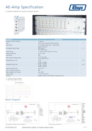
AE-Amp Acoustic Emission Amplifier
- Number of Input Channels: 2 channels
- Gain Options: Selectable at 0 dB, 20 dB, 40 dB, and 60 dB (0 dB is software selectable)
- Input Stage: AC coupled voltage input, single-ended
- Compatible Sensor Types: Passive AE sensors, JFET sensors, ICP/IEPE sensors (other types available on request)
- Sensor Power: 4 - 50 mA current source, 25 V max
- Output Impedance: 50 Ω ± 0.5%
- Input Noise: TBD
- Max. Output Voltage Swing: ± 9 V (no load), ± 4.5 V (load = 50 Ω)
- Bandwidth (Low Cut): 5 kHz at -3 dB
- Bandwidth (High Cut): Varies with gain: 5.0 MHz (0 dB), 3.0 MHz (20 dB), 2.0 MHz (40 dB), 700 kHz (60 dB) at -3 dB
- Gain Error @ 100 kHz: Max ± 1%
- Input/Output Connector: BNC
- High Voltage Pulse Through: Max 500 V
- Power Supply: 12 V DC, max 8 W
- Interface: RS485 / USB via AE-HV-MUX or Rack Base Unit
The block diagram illustrates the AE-Amp-Box or AE-Amp-P used in AE-HV-MUX and Amp-BU-20-AE configurations, showing bandwidth variations across different gain settings.
Catalog excerpts
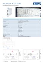
AE-Amp Specification 2 Channel Amplifier for Acoustic Emission Sensors Parameter Number of Input Channels Gain Input Stage Specification 2 channel 0 dB / 20 dB / 40 dB / 60 dB selectable AC coupled voltage input, single ended passiv AE sensors JFET sensors ICP / IEPE sensors 4 - 50 mA current source, 25 V max. 50 Ω ± 0.5% TBD ± 9 V (no Load) ± 4.5 (Load = 50 Ω) 5 kHz 00 dB : 5.0 MHz 20 dB : 3.0 MHz 40 dB : 2.0 MHz 60 dB : 700 kHz max ± 1% BNC max. 500 V 12 V DC, max. 8 W RS485 / USB over AE-HV-MUX or Rack Base Unit Compatible Sensor Types Sensor Power Output Impedance Input Noise Max. Output Voltage Swing Bandwidth (Low Cut) Bandwidth (High Cut) Gain Error @ 100 kHz Input / Output Connector High Voltage Pulse Through Power Supply Interface * 1 ) 0 dB only software selectable * 2 ) Other sensor types on request AE-Amp Bandwidth 0 dB Block Diagram AE-Amp-Box or AE-Amp-P used int AE-HV-MUX Specifications subject to change without
Open the catalog to page 1All Elsys AG catalogs and technical brochures
 EL-Att3-1000
1 Page
 EL-Att3-100
1 Page
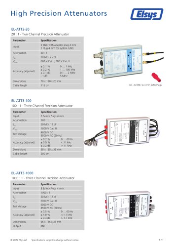 EL-ATT2-20
1 Page
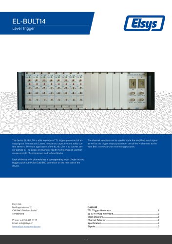 EL-BULT14
3 Pages
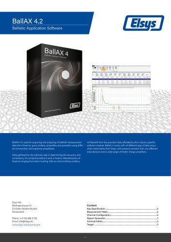 Datasheet BallAX 4
3 Pages
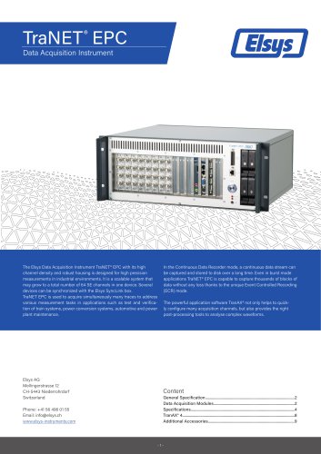
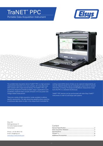 Datasheet TraNET PPC
9 Pages
 TraNET EPC
9 Pages
 TraNET FE 408 DP
5 Pages


Archived catalogs
 Reluctance Triggers EL-TRG_R
4 Pages
 Elsys Product Overview
15 Pages
 EL-DAQ Data Logger Solution
3 Pages
 EL-BULT14
3 Pages
 TraNET EPC Datasheet
9 Pages


- Rectangular housing
- Data logger
- Process software
- Temperature datalogger
- Measurement software
- Signal amplifying integrated circuit
- Protection housing
- Generator
- Electronic equipment enclosure
- Programming software solution
- Datalogger without display
- IP65 housing
- Monitoring datalogger
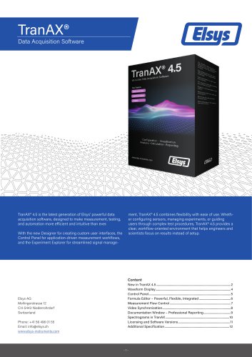
- Data acquisition software
- Programmable datalogger
- Data acquisition unit
- Pressure logger
- CAM software
- Measuring amplifier
- Voltage amplifier