Installation and arrangement of universal drivelines
1 /6Pages
Installation and arrangement of universal drivelines
1 /6Pages
Catalog excerpts

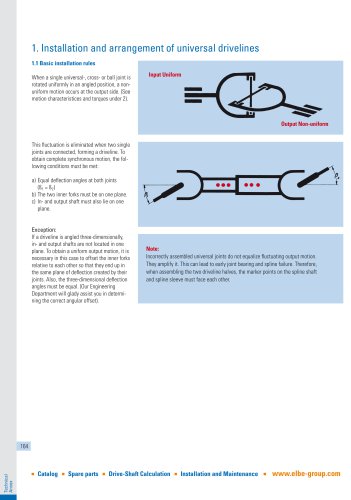
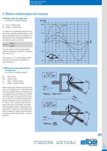
1. Installation and arrangement of universal drivelines 1.1 Basic installation rules When a single universal-, cross- or ball joint is rotated uniformly in an angled position, a nonuniform motion occurs at the output side. (See motion characteristices and torques under 2). Input Uniform Output Non-uniform This fluctuation is eliminated when two single joints are connected, forming a driveline. To obtain complete synchronous motion, the following conditions must be met: a) Equal deflection angles at both joints (ß1 = ß2) b) The two inner forks must be on one plane. c) In- and output shaft must also lie on one plane. Exception: If a driveline is angled three-dimensionally, in- and output shafts are not located in one plane. To obtain a uniform output motion, it is necessary in this case to offset the inner forks relative to each other so that they end up in the same plane of deflection created by their joints. Also, the three-dimensional deflection angles must be equal. (Our Engineering Department will glady assist you in determining the correct angular offset). Note: Incorrectly assembled universal joints do not equalize fluctuating output motion. They amplify it. This can lead to early joint bearing and spline failure. Therefore, when assembling the two driveline halves, the marker points on the spline shaft and spline sleeve must face each other. Technical Annex Spare parts Drive-Shaft Calculation
Open the catalog to page 1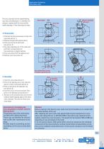
Application Guidelines Calculation data The cross Journals and the needle bearing cups wear simultaneously. It is therefore necessary to replace both the cross and the needle bearings, if they show signs of wear. Knock lightly Push in, if possible with press 1.2 Disassembly 1. Eliminate the tension between circlips and cups (see picture 1). 2. Remove circlips (with special pliers). 3. Press out one cup at each yoke (see picture 2). 4. Grip cups extending out of the yokes and pull them out (see picture 3). Use aluminium or plastic hammer. 5. Press out and pull off the opposite cup. 6. Remove cross...
Open the catalog to page 2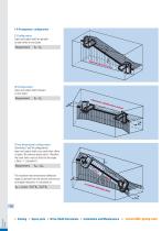
1.4 Arrangement configuration Z-Configuration: Input and output shaft are parallel to each other on one plane. Requirement: W-Configuration: Input and output shaft intersect on one plane. Requirement: Three-dimensional configuration: (Combined Z and W configuration) Input and output shaft cross each other offset in space. No common plane exists. Therefore the inner forks must be offset by the angle (See 1.1 „Exception“). Requirement: The resultant three-dimensional deflection angle ßR derived from the vertical and horizontal angular deviation, is calculated as: Technical Annex Spare parts Drive-Shaft...
Open the catalog to page 3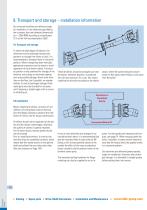
9. Transport and storage – installation information Our universal drivelines are delivered ready for installation. If not otherwise specified by the customer, they are balanced dynamically at n = 2000 RPM according to classification Q 16 of the VDI recommendation 2060. 9.1 Transport and storage To retain the high degree of balance, the drivelines must be protected during transportation or storage from blows or jolts. It is recommended to transport them in horizontal position. When transporting them vertically, appropriate measures must be taken to avoid separation of the driveline halves. A horizontal...
Open the catalog to page 4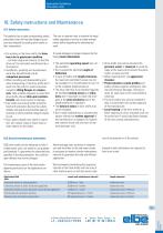
Application Guidelines Calculation data The operator has to take corresponding safety precautions that will exclude dangers to persons and material by rotating drive shafts or their components. • On working on the drive-shafts the drive has to be in quiescent condition - set down engine and secure, so that the drive can't be activated unauthorised by a third person. • Installation, assembly and maintenance work may be performed only by competent personnel. • When installing and disassembling and when transporting of the drive shafts don't reach into the joints to avoid contusions caused by tilting...
Open the catalog to page 5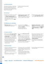
ELBE cardan-drive-shafts are normally equipped with 3 cone-grease-nipples DIN 71412. Thereby every joint will be greased over per grease nipple, the third nipple serves for relubrication of the spline profile. This nipple is omitted for plastic-coated lenght extensions. • Temperature range up to approx. +250°C, greases of the consistency 2. Special versions up to +250°C are partly available. 10.3.1 Lubricants • Temperature range -30°C up to max. +70°C: For relubrication of the drive shafts use only lithium-saponified greases of consistency class 2 with penetration 265/295 and drop point approx....
Open the catalog to page 6All ELSO Elbe catalogs and technical brochures
 ELBE Sensing Technology EST
2 Pages
 Application Guidelines
15 Pages