Application Guidelines
1 /15Pages
Application Guidelines
1 /15Pages
Catalog excerpts
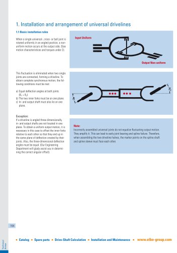
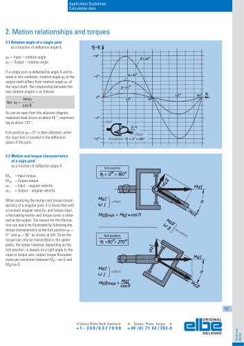
Application Guidelines Calculation data 2. Motion relationships and torques 2.1 Rotation angle of a single joint as a function of deflection angle ß 1 = Input – rotation angle 2 = Output – rotation angle If a single joint is deflected by angle ß and rotated in this condition, rotation angle 2 of the output shaft differs from rotation angle 1 of the input shaft. The relationship between the two rotation angles is as follows: tan 2 = As can be seen from the adjacent diagram, maximum lead occurs at about 45 °, maximum lag at about 135°. Fork position 1 = 0° is then obtained, when the input fork is located in the deflection plane of the joint. 2.2 Motion and torque characteristics of a sigle joint as a function of deflection angle ß Output fork position fork position = Input torque = Output torque = Input – angular velocity = Output – angular velocity When analyzing the motion and torque characteristics of a singular joint, it is found that with a constant angular velocity- and torque input, a fluctuating motion and torque curve is obtained at the output. The reason for this fluctuation can easily be illustrated by following the torque characteristics at the fork position 1 = 0° and 1 = 90° as shown at left. Since the torque can only be transmitted in the spider plane, the spider however, depending on the fork position, is always at a right angle to the input or output axis, output torque fluctuates twice per revolution between MdI · cos ß and MdI/cos ß. fork position Service Phone North America Service Phone Europe
Open the catalog to page 1
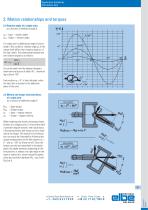
The transmitted power, however, is constant, if you disregard friction losses in the bearings. Therefore, the following applies: NI = NII = Constant MdI · I = MdII · II = Constant MdI MdII For fork position 1 = 0° we obtain: MdI MdII min Antrieb Input and for fork position 1 = 90°: MdI MdII max Gabelstellung fork position Antrieb Output 2.3 Motion and torque characteristic of a universal driveline as a function of deflection angles ß1 and ß2 Section 2.2 illustrates that angular velocity and torque at the output of a single joint follow a sinusoidal pattern with a 180° cycle. Maximum angular...
Open the catalog to page 2
Application Guidelines Calculation data 3. Fluctuation rate As explained under 2.1, on a single joint the output velocity deviates from the input velocity. This means, the speed ratio is not uniform. This non-uniformity (fluctuation) can be calculated as a dimensionless value: 3.2 Universal driveline (2 joints connected in series) 3.3 Universal driveline with more than two joints If the preconditions listed in Chapter 1 for obtaining a complete motion compensation cannot be met, it must be aimed for that: U 0,0027. Design requirements might dictate the use of a universal driveline that employs...
Open the catalog to page 3
4. Offset angle On drivelines with three-dimensional deflection angles, input and output shaft are not located in one plane. This results, if no special measures are taken, in a non-uniform output motion. The constantly repeating acceleration and deceleration unleashes inertia forces which can greatly reduce the life of the joints. However, not only the driveline, the driven equipment also is subjected to these forces and vibration caused by them. To avoid this, the inner forks must be offset relative to each other such that each fork ends up in the plane of deflection of its joint. The angle...
Open the catalog to page 4
Application Guidelines Calculation data 5. Additional moments on the drive line; Bearing loads on the input and output shaft In Section 2.2 it was shown that the torque is transmitted only in the spider plane and that depending on the fork position, the spider can be perpendicular either to the input axis or the output axis. What additional forces and moments this causes on the driveline as well as on the bearings of the input and output shaft, is Bearing loads on input and output shaft with Z-arrangement Side view Side view Driveline-center part stressed in bending Driveline-center part stressed...
Open the catalog to page 5
To size universal drivelines properly, various conditions and factors must be considered. In view of the multitude of possible applications, exact, generally valid rules cannot be provided. The following information is therefore used for the first rough determination of size. In case of doubt, we will gladly compute the required joint sizes for you and, in this context, we like to refer to the technical questionnaires starting on page 189. The max. permitted torques Mdmax stated for the individual drive-shaft sizes apply normally only for short-term peak loads. Mdnom: Nominal torque for pre-selection...
Open the catalog to page 6
Application Guidelines Calculation data 6.4 Life expectancy-Diagram There are also methods of obtaining the modified life expectancy. In this case varying survival probabilities, material quality and operating conditions are taken into account. The present technical know how does not allow statements to be made about variations in life expectancy performance resulting from differences in steel quality (grain, hardness, impurities). For this reason, no guidelines have been set in the International Standards. expectancy and accordingly, a life expectancy diagram valid for universal use. All pertinent...
Open the catalog to page 7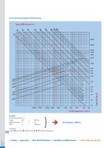
6.5 Life expectancy diagram, Needle bearing Speed, RPM n (in min-1) ^ Example Universal driveline 0.113 Torque Md Life expectancy = 6900 hrs. Procedure: Torque ^ Joint size ^ Defelction angle ^ RPM ^ Life expectancy ■ Catalog ■ Spare parts ■ Drive-Shaft Calculation ■ Installation and Maintenance ■ www.elbe-group.com
Open the catalog to page 8
Application Guidelines Calculation data 6.6 Life expectancy diagram, Roller bearing Speed, RPM n (in min-1) ^ 40000 Example Universal driveline 0.158 Torque Md Life expectancy = 7000 hrs. Procedure: Torque ^ Joint size ^ Defelction angle ^ RPM ^ Life expectancy ■ Service Phone North America ■ ■ Service Phone Europe ■ elDe GELENKE
Open the catalog to page 9
6.7 RPM and deflection angle As shown in 2.3 by taking certain precautions, a constant output can be obtained on a universal driveline. The center part, however, still retains a non-uniform motion; it is subjected twice per revolution to an acceleration and deceleration. The resulting acceleration torque caused this way is a function of the mass moment of inertia of the driveline‘s center part as well as of rpm and deflection angle. When regarding smoothness of operation and wear, the product of rpm and deflection angle should not be too high. For use in general mechanical engineering, appropriate...
Open the catalog to page 10All ELSO Elbe catalogs and technical brochures
 ELBE Sensing Technology EST
2 Pages