- Catalogs
- Elma Electronic AG
- Remote Audio Plus_Datasheet_E
- Company
- Products
- Catalogs
- News & Trends
- Exhibitions
Remote Audio Plus_Datasheet_E
1 /7Pages

Remote Audio Plus_Datasheet_E
1 /7Pages
Catalog excerpts

AUDIO SOLUTION REMOTE AUDIO PLUS Product description MAIN FEATURES IR CONTROLLED MOTOR DRIVER KIT FOR ELMA’S TYPE A4, A47 AND 04 SWITCHES › › › › › › REMOTE AUDIO PLUS IR remote controlled with IR teach-in function Adjustable to different switch types Push button and host control remote options Relay mute function Zero EMI emission when not actuated Switch feel virtually not affected by motor (LIN motor option) Customer supplies their own remote Note torque limits per motor type REMOTE AUDIO PLUS with LIN motor 11/65/EU) Remote Audio Plus with LIN motor Standard version with standard motor High-end audio and Pro audio Industrial controls STANDARD VERSION with standard motor * Switch and IR remote unit are not included
Open the catalog to page 1
AUDIO SOLUTION REMOTE AUDIO PLUS ELMA Your Solution Partner Dimensions, pin assignment and circuit diagramSWITCH DESIGN PIN ASSIGNMENT CONTROL MODULE IR RECEIVER Solder jumper ♦12VDC Power Gno input DC motor output 23 (oreen) 2A (btack) Stepper I a (btuel motor 18 (red) t/otor tor due adjustment (C.w. increasing torque) CIRCUIT DIAGRAM FOR RELAY MUTE FUNCTION In Out GND In Out GND Dimensions in mm Tolerances according to DIN ISO 2768-1 (m), unless otherwise specified
Open the catalog to page 2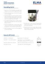
AUDIO SOLUTION REMOTE AUDIO PLUS Assembling the kit 1. ount the two 30 mm stand-offs to the stepper motor M using the two set screws (do not tighten the set screws). 2. Feed the switch drive linkage onto the shaft of the stepper motor (do not tighten). 3. ssemble the stepper motor with its stand-offs and the linA kage onto the control module using the two M3 screws (be careful when feeding the linkage through the position sensor in the middle of the control module). 4. wist together the stepper motor’s wires (blue with red, T green with black) and solder them to the control module (see pin allocation)....
Open the catalog to page 3
AUDIO SOLUTION REMOTE AUDIO PLUS ELMA Your Solution Partner End stop calibration and IR teach-in USING THE TACT SWITCH 1. Push the tact switch until the LED flashes for approximately 1 second. 2. Turn the switch to the fully right position and quickly push the tact switch. The LED flashes for approximately 300 milliseconds for confirmation. 3. Turn the switch to the fully left position and quickly | long push the tact switch. Quick push: The LED flashes for approximately 300 milliseconds for confirmation. Long push: Jumping to #5 (used when no IR receiver connected, e.g. in slave mode). 4. Quickly...
Open the catalog to page 4
AUDIO SOLUTION REMOTE AUDIO PLUS #1 CLASSIC SINGLE Auf UNIT OPERATION Ab 12 RAPLUS The classic mode of300 mm operationVDC Versorgung a single unit incorporates Max. 12 IR in VDC Versorgung that is either manually or IR controlled. The versatile control +12 GND GND IR Auf Vcc +12 GND module can be adjusted to individual end stop positions, Ab RAPLUS switch resolutions and operating speeds. Any type of NEC Max. 300 mm RAPLUS IR in compliant IR protocol can be used and «taught in». The GND IR Vcc power requirements are 12 VDC nominal at 1.2 A (2.4 A GND SER with LIN motor) peak current VDC Versorgung...
Open the catalog to page 5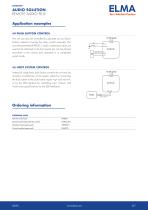
Keep GND wire short, use >= 0.25 mm 2 (AWG23) RAPLUS Slave-Einheit (rechts) AUDIO SOLUTION RAPLUS REMOTE AUDIO PLUS Master-Einheit Max. 300 mm Application examples Aktiviere Löt-Brücke Bei Master-Einheit! RAPLUS Master unit IR in (left) RAPLUS Slave unit (right) Activate soldering jumper at master unit! #4 PUSH BUTTON CONTROL 12 VDC Versorgung The unit can also be controlled by separate up and down buttons instead of turning theAuf rotary switch manually. This +12 GND PB Aufauf way the assembled RAPLUSAb switch combination does not / PB ab Ab RAPLUS need to be attached to the front panel, but...
Open the catalog to page 6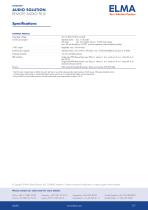
AUDIO SOLUTION REMOTE AUDIO PLUS ELMA Your Solution Partner Specifications CONTROL MODULE Operating voltage: Current consumption: 5 VDC output: Switch torque capacity: Indexing resolution: SER interface: 8 to 15 VDC (12 VDC nominal) Standard motor: max. 1.2 A peak2 max. 20 mA stand-by (at 12 VDC, no motor operation, without display module) Regulated, max. 100 mA load Standard motor: max. 6 Ncm | LIN motor: max. 10 Ncm (limitable by trim pot, at 12 VDC) 12, 24 or 48 (47) positions Single pulse PPM (low-active): «up» 500 ps | «down» 1 ms | «mute on» 2 ms | «mute off» 4 ms (all ±20 %) Single pulse...
Open the catalog to page 7All Elma Electronic AG catalogs and technical brochures
 iD-Box 16_Datasheet_E
2 Pages
 Defense
44 Pages
 Railway
17 Pages
 Compact Case 20 Datasheet
4 Pages
 Artificial Intelligence
4 Pages
 Unibox 14_Datasheet_E
19 Pages
 Guardbox 33_Datasheet_E
16 Pages
 Systemkit 12K_Datasheet_E
25 Pages
 Stylebox 15 e-motion_Datasheet_E
32 Pages
 E33 Encoder_Datasheet_E
9 Pages
 E37 Encoder_Datasheet_E
7 Pages
 07_C07A Coded Switch_Datasheet_E
10 Pages
 C07 Concentric_Datasheet_E
6 Pages
 M07 Coded Switch_Datasheet_E
5 Pages
 Classic Collet Knobs_Datasheet_E
11 Pages
 LED_Datasheet_E
6 Pages
 Elos Box 54_Datasheet_E
2 Pages
 Varietybox 35_Datasheet_E
10 Pages
 Guardbox 33 easy_Datasheet_E
5 Pages
 Ecokit 11_Datasheet_E
9 Pages
 Slimkit 10_Datasheet_E
6 Pages
 Corporate Overview
12 Pages
 K1 Metal Knobs_Datasheet_E
3 Pages
 Brochure iD-Box 16_E
8 Pages
 12R2 Rugged Chassis
2 Pages


Archived catalogs
 ELOS Elma Open System
4 Pages
 Power Supplies
8 Pages
 19" Frontpanels
2 Pages
 Rotary Switches Brochure
4 Pages
 Subrack 38_Brochure_E
6 Pages
 Brochure Shapebox 22_E
4 Pages
 Brochure BT Box 24_E
4 Pages
 C08 Coded Switch_Datasheet_E
6 Pages
 C16 Coded Switch_Datasheet_E
3 Pages
 E18 Encoder_Datasheet_E
7 Pages
 C15 Coded Switch_Datasheet_E
3 Pages
 VITA Type 12 Chassis Platforms
32 Pages
 FLEXCOM
4 Pages
 VITA Catalog
93 Pages
 Brochure Railway Solutions
16 Pages
 Surelock Card Retainers
8 Pages
 Rugged Cabinets
2 Pages
 Brochure Embedded Computers
28 Pages
 Brochure VPX and Open VPX
28 Pages
 PRODUCTS FOR SCIENTIFIC RESEARCH
20 Pages
 8016G-RS422-PMC-adapter
2 Pages
 Datasheet Type 38 Cabinet
3 Pages
 CompactPCI Serial
16 Pages
 VPX and OpenVPX by ELMA
28 Pages
 9289 XMCStor
2 Pages
 Customisation_and_Services_E
16 Pages
 General_Accessories_E
86 Pages
 A_Elmaset_19Chassis_and_Sub_Rack_E
148 Pages
 Desktop_and_Compact_Cases_E
261 Pages
 19inch_Accessories_E
18 Pages
 PICMG
PICMG136 Pages
 Elmaset_Frontpanels_Handles_E
80 Pages
 Elma RS Catalog_E
194 Pages
 The Elma OpenVPX ecosystem
4 Pages
 Banana Socket_Datasheet_E
2 Pages
 MicroTCA
12 Pages
 mtca4
mtca412 Pages


