- Catalogs
- Elma Electronic AG
- Elmaset_Frontpanels_Handles_E
- Company
- Products
- Catalogs
- News & Trends
- Exhibitions
Elmaset_Frontpanels_Handles_E
1 /80Pages

Elmaset_Frontpanels_Handles_E
1 /80Pages
Catalog excerpts

Front Panels, Handles and Plug-in Units
Open the catalog to page 2
1. Front Panels for Sub Racks and Enclosures • Flat front panels • EMC flat front panels • Fan front panels • Hinged front panels
Open the catalog to page 3
• Fan Modules Vertical • Fan Modules Horizontal • Fan and Fan Speed Control
Open the catalog to page 4
1: Fr ont Pa n e ls fo r S u b R a c k s a nd Enc l o s u r e s 1.1 Flat Front Panels 1.1.1 Front Panel Screws 1.2.1 EMC Filler Panel with EMC Gasket 1.2.2 EMC Filler Panel without EMC Gasket 1.2.3 EMC Flat Front Panels 1.2.5 Perforated EMC Front Panel 84 HP 1.3.1 Fan Front Panel 84 HP for Vertical Ventilation 1.3.2 Fan Front Panel for Horizontal Ventilation 1.3.3 Fan Front Panels for Direct Fan Mounting 1.4 Hinged Front Panels 1.4.1 Top / Bottom-Hinged Front Panel 1.4.2 EMC Top / Bottom-Hinged Front Panel 1.4.3 Side-Hinged Front Panel
Open the catalog to page 6
1.1 Flat Front Panels • For sub racks and enclosures, solid • Aluminium 2.5 mm, clear anodised (non-conductive) • Scope of delivery: • Flat front panel • Front panel screws, see below • 2 HP version: screw retainer can not be fitted 1.1 Flat Front Panels for Sub Racks and Enclosures, Solid
Open the catalog to page 7
1.2 EMC Flat Front Panels “Electromagnetic comptability is the ability of a system to operate in the intended environment without causing or suffering unacceptable degradation of performance due to unintentinal electromagnetic radiation or response.” The EMC characterstics of a system therefore consist of an appropriate immunity from interference (noise immunity) and a limited emission of interference (noise emission). Elma’s EMC concept describes three levels of electromagnetic shielding performance (Performance Level). The attenuation levels will simplify the selection of sub racks for the...
Open the catalog to page 8
1: Front Panels for Sub Racks and Enclosures1.2.1 EMC Filler Panel with EMC Gasket • High stability (U-profile) • Extruded aluminium • Pressed-in centring pin and bushes M2.5 • Front side clear anodised, rear side conductive • Scope of delivery: • EMC front panel incl. pressed-in centering pin and bushes M2.5 • EMC-gasket see below • Front panel screw see below
Open the catalog to page 9
1.2.2.2 Spacer for EMC Front Panel Flat • EMC-Level: Advanced • Scope of delivery: • 1 spacer incl. gasket • 2 Torx sheet metal screws 2.9 x 6.5; size T 10
Open the catalog to page 10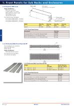
_____________ 1: Front Panels for Sub Racks and Enclosures 1.2.4 Superior EMC Level • Scope of delivery: • EMC flat front panel • Contact angle, incl. screws • EMC gasket for contact angle • EMC gasket for front extrusion/front panel • Front panel screws, see below • Front panel width 42 HP = 4 screws • Front panel width 63 HP = 6 screws • Front panel width 84 HP = 8 screws Contact angle with conductive tape EMC gasket full height (side/front panel) 1.2.5 Perforated EMC Front Panel 84 HP • Front anodised, rear conductive • Advanced EMC level • Width: 84 HP • Scope of delivery: • Perforated flat...
Open the catalog to page 11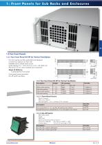
1.3 Fan Front Panels1.3.1 Fan Front Panel 84 HP for Vertical Ventilation • Fan front panels are flat, perforated and designed to ensure an optimum air flow rate • Available with or without switch cut-out (switch opening 1 U = 12.3 x 27.2 mm / 2 U = 22 x 30.6 mm) • Aluminium 2.5 mm, clear anodised (non-conductive) • Scope of delivery: • 1 perforated fan front panel • Front panel screws see below • On-off switch see below 1.3.1 Fan Front Panel 84 HP for Vertical Ventilation
Open the catalog to page 12
• Aluminium 2.5 mm, clear anodised (non-conductive) • Scope of delivery: • 1 perforated fan front panel • Front panel screws see below 1.3.2 Fan Front Panel for Horizontal Ventilation Height 1.3.2.1 Front Panel Screws • Set of 10 screws • With screw retainer • Fan front panel width up to 8 HP = 2 screws; > 12 HP = 4 screws 1.3.3.2 Assembly Material for Fan Mounting Description
Open the catalog to page 13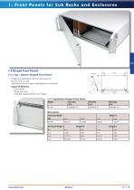
1.4 Hinged Front Panels 1.4.1 Top / Bottom-Hinged Front Panel • Hinges are attached to the front extrusions of the sub rack or case • Aluminium 2.5 mm, clear anodised (non-conductive) • Scope of delivery: • Front panel • Hinge extrusion • Assembly material M2.5, incl. hinges 1.4.1 Top/Bottom-Hinged Front Panel
Open the catalog to page 14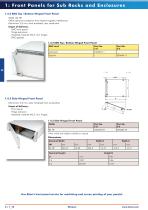
1.4.2 EMC Top / Bottom-Hinged Front Panel • Width: 84 HP • Offers optimum protection from electromagnetic interference • Aluminium 2.5 mm, front anodised, rear conductive • Scope of delivery: • EMC front panel • Hinge extrusions • Assembly material M2.5, incl. hinges • EMC gaskets 1.4.2 EMC Top / Bottom-Hinged Front Panel Use Elma's front panel service for machining and screen printing of your panels! C | 1_10 Elmaset www.elma.com
Open the catalog to page 15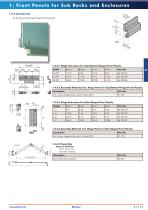
• To build up customised hinged front panels 1.4.4.1 Hinge Extrusions for Top/Bottom-Hinged Front Panels
Open the catalog to page 16
2 : Front Pan e ls fo r Plu g -I n Uni t s 2.1 Plug-In Units acc. to IEC 2.1.1 Extruded Front Panel 2.1.2 Front Panel with Cutout for IEC Ejector Handle 2.2.1 EMC Filler Panel without Openings 2.2.2 EMC Front Panels for IEC Plug-In Units with Cutout for Ejector Handle acc. to IEC 2.3 Plug-In Units acc. to IEEE 2.3.1 EMC Front Panels Aluminium with EMC Gasket acc. IEEE 2.3.2 Injector/Ejector Handles acc. to IEEE 2.3.3 Card Holder and Coding Pins acc. to IEEE 2.5 Plug-In Units “Ergonomic” acc. to AdvancedTCA 2.5.1 EMC ATCA Front Panels “Ergonomic” 2.5.2 EMC Front Panel 8 U x 6 HP Aluminium 2.5.3...
Open the catalog to page 17
2: Fr ont Pa n e ls fo r P l u g -I n Uni t s 2.6 Plug-In Units “Classic” acc. to AdvancedTCA 2.6.1 Plug-In Units “Classic” 2.6.4 Captive Screw M3 and Latch Spring Clip 2.6.6 Microswitch for Injector/Ejector Handle 2.7 PMC Mezzanine Front Panels 2.8 FMC Mezzanine Front Panels
Open the catalog to page 18
2.1 Plug-In Units acc. to IEC2.1.1 Extruded Front Panel Aluminium 2.5 mm, clear anodised (non-conductive) PCB mounting lugs are formed on the rear face of the panel No PCB fixing screws on the front face of the panel, leaving more space for silk screening and mounting front panel components Suitable for all sub racks and cases Thickness of the mounting lugs (3.48 mm) allows PCBs to be mounted on either side of the lugs Drill marks at rear for handle-fixing holes Scope of delivery: • Extruded front panel, clear anodised Front panel screws see below 2.1.1 Extruded Front Panels, without Openings
Open the catalog to page 19All Elma Electronic AG catalogs and technical brochures
 iD-Box 16_Datasheet_E
2 Pages
 Defense
44 Pages
 Railway
17 Pages
 Compact Case 20 Datasheet
4 Pages
 Artificial Intelligence
4 Pages
 Unibox 14_Datasheet_E
19 Pages
 Guardbox 33_Datasheet_E
16 Pages
 Systemkit 12K_Datasheet_E
25 Pages
 Stylebox 15 e-motion_Datasheet_E
32 Pages
 E33 Encoder_Datasheet_E
9 Pages
 E37 Encoder_Datasheet_E
7 Pages
 07_C07A Coded Switch_Datasheet_E
10 Pages
 C07 Concentric_Datasheet_E
6 Pages
 M07 Coded Switch_Datasheet_E
5 Pages
 Classic Collet Knobs_Datasheet_E
11 Pages
 LED_Datasheet_E
6 Pages
 Elos Box 54_Datasheet_E
2 Pages
 Varietybox 35_Datasheet_E
10 Pages
 Guardbox 33 easy_Datasheet_E
5 Pages
 Ecokit 11_Datasheet_E
9 Pages
 Slimkit 10_Datasheet_E
6 Pages
 Corporate Overview
12 Pages
 K1 Metal Knobs_Datasheet_E
3 Pages
 Brochure iD-Box 16_E
8 Pages
 12R2 Rugged Chassis
2 Pages


Archived catalogs
 ELOS Elma Open System
4 Pages
 Power Supplies
8 Pages
 19" Frontpanels
2 Pages
 Rotary Switches Brochure
4 Pages
 Subrack 38_Brochure_E
6 Pages
 Brochure Shapebox 22_E
4 Pages
 Brochure BT Box 24_E
4 Pages
 C08 Coded Switch_Datasheet_E
6 Pages
 C16 Coded Switch_Datasheet_E
3 Pages
 E18 Encoder_Datasheet_E
7 Pages
 C15 Coded Switch_Datasheet_E
3 Pages
 VITA Type 12 Chassis Platforms
32 Pages
 FLEXCOM
4 Pages
 VITA Catalog
93 Pages
 Brochure Railway Solutions
16 Pages
 Surelock Card Retainers
8 Pages
 Rugged Cabinets
2 Pages
 Brochure Embedded Computers
28 Pages
 Brochure VPX and Open VPX
28 Pages
 PRODUCTS FOR SCIENTIFIC RESEARCH
20 Pages
 8016G-RS422-PMC-adapter
2 Pages
 Datasheet Type 38 Cabinet
3 Pages
 CompactPCI Serial
16 Pages
 VPX and OpenVPX by ELMA
28 Pages
 9289 XMCStor
2 Pages
 Customisation_and_Services_E
16 Pages
 General_Accessories_E
86 Pages
 A_Elmaset_19Chassis_and_Sub_Rack_E
148 Pages
 Desktop_and_Compact_Cases_E
261 Pages
 19inch_Accessories_E
18 Pages
 PICMG
PICMG136 Pages
 Elma RS Catalog_E
194 Pages
 The Elma OpenVPX ecosystem
4 Pages
 Banana Socket_Datasheet_E
2 Pages
 MicroTCA
12 Pages
 mtca4
mtca412 Pages


