- Catalogs
- Elma Electronic AG
- Elma RS Catalog_E
- Company
- Products
- Catalogs
- News & Trends
- Exhibitions
Elma RS Catalog_E
1 /194Pages

Elma RS Catalog_E
1 /194Pages
Catalog excerpts
Rotary Switches PRODUCT CATALOG SYSTEM SOLUTIONS ENCLOSURE & COMPONENTS ROTARY SWITCHES
Open the catalog to page 1
REMOTE AUDIO PLUS 180 ENCODER | HALL SENSOR SWITCHES 191
Open the catalog to page 3
Titel Titel Titel Titel zweite Zeile Customer-specific solutions Das Nonsequam ab idit quam fuga. Nem quate comnihitis quia sit, abore volo eaOur engineers porecum nimus aut qui aut et, nonse volupta to realize the special rumqu odiorem have the necessary know-how and resources tempeli busani nobis requirements of post, ut ute cus vitiatur antium volupta et aliati numque our customers quickly and affordably. nullestiis magnisc ientiore estrum eatur, ipic tenimet occus natios ma dendict otatece pereror ad ma ate aut fuga. Musam andae pos et hitasit idelit, unt.
Open the catalog to page 4
CUSTOMER-SPECIFIC SOLUTIONS Why Elma? BECAUSE WE ARE «YOUR SOLUTION PARTNER» FIRST-CLASS CUSTOMER SUPPORT Elma's rotary switches encompasses a broad range of switching and indicating solutions, control knobs, LEDs and banana sockets. They are the haptic and optical interface for commands between human and machine. Our products appeal with high quality, reliability and performance. They are designed for simple, but especially for demanding applications. It is the reason why we are leading in many markets. Our products are being developed in Switzerland and USA. The production plants are in Switzerland...
Open the catalog to page 5
Titel Titel Titel Titel zweite Zeile Multi rotary switches Das Nonsequam ab idit quam fuga. Nem quate comnihitis quia sit, abore volo eaOur multi-functional switches with Hall-effect or mechanical contact system nobis rumqu odiorem porecum nimus aut qui aut et, nonse volupta tempeli busani are ready to provide a reliable long-lasting output. et aliati numque post, ut ute cus vitiatur antium volupta nullestiis magnisc ientiore estrum eatur, ipic tenimet occus natios ma dendict otatece pereror ad ma ate aut fuga. Musam andae pos et hitasit idelit, unt.
Open the catalog to page 6
> Selector or coded switch with push button > Rugged design > Sealing up to IP68 > High switching torques: Up to 20 Ncm > Up to 48 switching positions > Operating temperature range: -45 to +85 °C > Various options and customizations > Not ITAR related jjl ELV (2000/53/EC) ’ 11/65/EU)
Open the catalog to page 7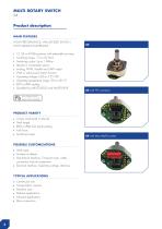
Product description MAIN FEATURES HIGH PERFORMANCE, HALL-SENSED SWITCH WITH VARIOUS INTERFACES > 12, 24 or 47/48 positions with selectable end stop > Switching torque: 1.5 to 20 Ncm > Switching cycles: Up to 1 Million > Absolut or incremental version > Analog, PWM, Parallel and UART output > With or without push button function > Operating voltage: 2.85 to 5.25 VDC > Operating temperature range: -30 to +85 °C > IP60 or IP68 sealing > Qualified by MIL-STD-202G and MIL-STD-810F PRODUCT VARIETY ■ Output incremental or absolut ■ Shaft length ■ IP60 or IP68 front panel sealing ■ Push force ■ Switching...
Open the catalog to page 8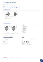
PIN ASSIGNMENT FFC Version MM Version 1. Vcc 2. GND 3. Bit 1/A (UART 1) 4. Bit 2/B (UART 2) 5. Bit 3 (UART 3) 6. Bit 4 (UART RQ) 7. Bit 5 (UART EN) 8. Push button 9. Analog out 10. PWM (Bit 6) 11. Vcc 12. GND 13. Analog out UART mode can be activated by solder bridge or UART EN (Pin #7) set to low. NUT LOCK WASHER AND HEX NUT (SUPPLIED) Dimensions in mm Tolerances according to DIN ISO 2768-1 (m), unless otherwise specified
Open the catalog to page 9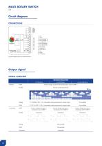
MULTI ROTARY SWITCH X4 Circuit diagram CONNECTIONS 1. Vcc 2. GND 3. Bit 1/A (UART 1) 4. Bit 2/B (UART 2) 5. Bit 3 (UART 3) 6. Bit 4 (UART RQ) 7. Bit 5 (UART EN) 8. Push button 9. Analog out 1 0. PWM (Bit 6) 11. Vcc 12. GND 13. Analog out External magnetic fields may interfere function. Output signal SIGNAL OVERVIEW INDEXING RESOLUTION 12 POSITIONS Absolute At every change of position the absolut position is sent to UART 1 Absolute Code Output (Gray) high 0° ≙ GNDd to 359° = Vcc, intermediate values proportional to rotation angle 0° ≙ 0 % to 359° = 100 %, intermediate values proportional to rotation...
Open the catalog to page 10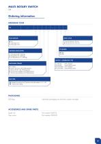
MULTI ROTARY SWITCH X4 Ordering information ORDERING CODE X4 PUSH BUTTON SHAFT STYLE N No P Push button 7 N S Push button 14 N INDEXING RESOLUTION OUTPUT | CONNECTOR TYPE SWITCHING TORQUE A 1.5 Ncm B 4 Ncm (2.5 Ncm with 47/48 positions) C 8 Ncm (5 Ncm with 47/48 positions) D 15 Ncm (not available with 47/48 positions) E 20 Ncm (not available with 47/48 positions) Absolute Absolute Incremental Incremental | FFC connector | Micro-MaTch socket | FFC connector | Micro-MaTch socket END STOP XX Number of positions (for 47 positions only odd numbers: 3, 5, 7...47) 00 Continuously rotating Individual...
Open the catalog to page 11
MECHANICAL DATA
Open the catalog to page 12
ENVIRONMENTAL DATA Operating temperature: Storage temperature: Humidity: Salt atmosphere against front panel: IP sealing against front panel: Vibration: Shock: -30 to +85 °C (IEC 60068-2.14) -40 to +85 °C (IEC 60068-2-14, MIL-STD202G, method 107G, condition B-3) < 93 % relative humidity (MIL-STD-202G, method 103B, condition B) Only with IP68 gasket (MIL-STD-810F, method 509.4) IP60 without sealing IP68 with shaft and front panel sealing (5 bar, 4 h) 29 Grms (MIL-STD-202G, method 214A, duration 15 min) 100 G (MIL-STD-202G, method 213B, condition C) MECHANICAL DATA FOR PUSH BUTTON Actuation force:...
Open the catalog to page 13
MAIN FEATURES 1 /2" SELECTOR SWITCH > Dimensions 0 1/2" > Switching mode: Shorting or non-shorting > 10, 12 and 16 selector switch positions > Switching torque: Up to 6 Ncm > Gold plated contacts > Rugged design > Sealing up to IP68 > Operating temperature range: -45 to +85 °C > Not ITAR related > Various options and customizations PRODUCT VARIETY POSSIBLE CUSTOMIZATIONS ■ Shaft style and material ■ Bushing style ■ Switching torque ■ Number of poles ■ Customizable end position ■ Interface solutions (socket plug) ■ Shaft diameter ■ Number of selector positions | indexing angles ■ Shaft styles...
Open the catalog to page 14
SWITCH DESIGN D-SHAFT FRONT PANEL SEALING IP68 sealing gasket 11 NO •t3-!L Dimensions in mm Tolerances according to DIN ISO 2768-1 (m), unless otherwise specified
Open the catalog to page 15
MULTI ROTARY SWITCH MR50 Dimensions and pin assignment DRILLING DIAGRAM AND FOOTPRINT 16 POSITIONS | 1 POLE Ø 9.6 bolt circle diameter Ø 9.6 bolt circle diameter Ø 9.6 bolt circle diameter Ø 9.6 bolt circle diameter Ø 9.6 bolt circle diameter View from the PCB Ø 9.6 outer bolt circle diameter Ø 9.6 inner bolt circle diameter Ø 9.6 outer bolt circle diameter Ø 9.6 inner bolt circle diameter Dimensions in mm Tolerances according to DIN ISO 2768-1 (m), unless otherwise specified
Open the catalog to page 16All Elma Electronic AG catalogs and technical brochures
 iD-Box 16_Datasheet_E
2 Pages
 Defense
44 Pages
 Railway
17 Pages
 Compact Case 20 Datasheet
4 Pages
 Artificial Intelligence
4 Pages
 Unibox 14_Datasheet_E
19 Pages
 Guardbox 33_Datasheet_E
16 Pages
 Systemkit 12K_Datasheet_E
25 Pages
 Stylebox 15 e-motion_Datasheet_E
32 Pages
 E33 Encoder_Datasheet_E
9 Pages
 E37 Encoder_Datasheet_E
7 Pages
 07_C07A Coded Switch_Datasheet_E
10 Pages
 C07 Concentric_Datasheet_E
6 Pages
 M07 Coded Switch_Datasheet_E
5 Pages
 Classic Collet Knobs_Datasheet_E
11 Pages
 LED_Datasheet_E
6 Pages
 Elos Box 54_Datasheet_E
2 Pages
 Varietybox 35_Datasheet_E
10 Pages
 Guardbox 33 easy_Datasheet_E
5 Pages
 Ecokit 11_Datasheet_E
9 Pages
 Slimkit 10_Datasheet_E
6 Pages
 Corporate Overview
12 Pages
 K1 Metal Knobs_Datasheet_E
3 Pages
 Brochure iD-Box 16_E
8 Pages
 12R2 Rugged Chassis
2 Pages


Archived catalogs
 ELOS Elma Open System
4 Pages
 Power Supplies
8 Pages
 19" Frontpanels
2 Pages
 Rotary Switches Brochure
4 Pages
 Subrack 38_Brochure_E
6 Pages
 Brochure Shapebox 22_E
4 Pages
 Brochure BT Box 24_E
4 Pages
 C08 Coded Switch_Datasheet_E
6 Pages
 C16 Coded Switch_Datasheet_E
3 Pages
 E18 Encoder_Datasheet_E
7 Pages
 C15 Coded Switch_Datasheet_E
3 Pages
 VITA Type 12 Chassis Platforms
32 Pages
 FLEXCOM
4 Pages
 VITA Catalog
93 Pages
 Brochure Railway Solutions
16 Pages
 Surelock Card Retainers
8 Pages
 Rugged Cabinets
2 Pages
 Brochure Embedded Computers
28 Pages
 Brochure VPX and Open VPX
28 Pages
 PRODUCTS FOR SCIENTIFIC RESEARCH
20 Pages
 8016G-RS422-PMC-adapter
2 Pages
 Datasheet Type 38 Cabinet
3 Pages
 CompactPCI Serial
16 Pages
 VPX and OpenVPX by ELMA
28 Pages
 9289 XMCStor
2 Pages
 Customisation_and_Services_E
16 Pages
 General_Accessories_E
86 Pages
 A_Elmaset_19Chassis_and_Sub_Rack_E
148 Pages
 Desktop_and_Compact_Cases_E
261 Pages
 19inch_Accessories_E
18 Pages
 PICMG
PICMG136 Pages
 Elmaset_Frontpanels_Handles_E
80 Pages
 The Elma OpenVPX ecosystem
4 Pages
 Banana Socket_Datasheet_E
2 Pages
 MicroTCA
12 Pages
 mtca4
mtca412 Pages


