DIM-2 | Staircase switch with dimming
1 /1Page

DIM-2 | Staircase switch with dimming
1 /1Page
Catalog excerpts
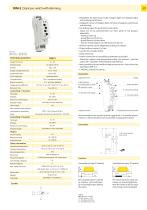
Overview table Method of phase regulation Control principal Output unit staircase switch with gradual dim-up/dim-down, level and length of illumination, all values are adjustable control by button/buttons (connected in parallel), short pressing ON/OFF, long pressing regulated brightness, memory recording as DIM-5, but dims all types of load, inbuilt protections against thermo and current overload, electronic fuse for controlled dimming of lights up to 2kW, with a possibility of module extention up to 20kW (el.bulbs and hallogen lights, also with ballast type C or L) Technical parameters is expanding power modul for controlled dimmer DIM-6 Supply terminals: as DIM-5, but for mounting under a wall-switch, into a wiring box, 3 wire connection (without neutral) is expanding power modul for controlled dimmer DIM-6 as DIM-14, but for mounting under a wall-switch, into an installation box Supply voltage Rated load resistive (el. bulbs, halogen lights) inductive (wound transformers) capacitive (electronic transformers) energy saving fluorescent lamps Catalogue page Type of dimmed load serves to dim all types of load, dimmable LED and energy saving bulbs included Supply indication: Time setting by: Supply voltage tolerance: Voltage range: DIM-2 | Staircase switch with dimming control unit for dimmers or electronic ballasts with analog control 0-10 V / 1-10 V serves to dim monochrome LED strips and RGB LED strips with power supply 12-24 V DC which are current-controlled Time deviation: 10 % - mechanical setting 5 % - set value stability Repeat accuracy: Temperature coefficient: Recovery time: Supply terminal A1 Supply indication Output indication Controlling input for switch - brightness setting t1 - dim-up time settting t3 - dim-down time setting t2 - time delay setting Power on control input: Note: * - with load over 300 VA is necessary to ensure sufficient cooling • Designated for dimming el. bulbs, halogen lights and halogen lights with winding transformers. • Intelligent control of halogen lights, function of gradual switching on and dimming. • Controlling inputs for push button and switch. • Values are set by potentiometers on front panel of the product, adjustable: - maximum dim-up - speed (fluency) of dim-up - speed (fluency) of dim-down - time for which a light is on with maximum dim-up. • All time intervals can be adapted according to a request. • Output without contact: 1x triac. • Load AC 5b (el. bulbs) 500 W. • Clamp terminals. • Parallel connection of controlling pushbuttons is possible. • Protection against over-temperature inside the product - switches output off + signalizes overheating by LED flashing. • Note: possibility of start and finish adjustment up on 1 hour, device has description DIM-2 1h. • 1-MODULE, DIN rail mounting. Impulse length: Glow-lamps: Max. amount of glow lamps Key to symbols bulbs, halogen lamps TYPE OF LOAD (symbols) low-voltage el.bulbs 12/24V wound transformers low-voltage el.bulbs 12/24V electronic transformers (measured with glow lamp 0.68 mA / 230 V AC) input: ESL dimmable compact fluorescent lamps Impulse length: Recommendation for mounting: leave a gap of min. 0.5 module (approx. 9 mm) on side of the device to ensure better cooling of the device. Terminals: Power on control input: Controlling input for push button Output Current rating: Dimmer with designated load: R - resistive L - inductive C - capacitive ESL - energy saving bulbs LED - LED bulbs Resistance load: Operating temperature: Storage temperature: Operating position: IP 40 from front panel / IP 10 terminals Protection degree: Overvoltage category: Controlled via input T2 (switch) Dim-up delay-down is started by a button. Cycle extension by re-pressing button (during the cycle). Recommendation for mounting modular dimmers: leave a gap of min. 0.5 module (approx. 9 mm / 0.4” ) on side of the device to ensure better cooling of the device. Other information Pollution degree: IPxx protection - under normal conditions: normal conditions are understood as such conditions of operating an electrical device, installation and power supply network for which the entire device is designed, produced and installed. Upon these normal conditions of use and upon normal maintenance, all protective devices must be effective throughout the entire expected service life of the product. T 2.5.A recommended back-up fuse Inductive load: Demonstrated symbols are informative Legend: Brightness: 10-100% t1- Dim-up time: 1-40 s t2 - Time delay: 0s-20min t3 - Dim-down time: 1-40s The switch starts the cycle and it stops on max.set brightness. After the switch is off,
Open the catalog to page 1All ELKO catalogs and technical brochures
 RFSA-66MI, RFSA-66M |
1 Page
 RFDEL-76M
1 Page
 Company profile
36 Pages
 We make World smarter
44 Pages
 Wireless electro-installation
64 Pages
 Highlights 2019
28 Pages
 Wired electro-installation
60 Pages
 Smart Home & Building Guide
36 Pages
 ELKO LIGHTING
32 Pages
 Product overview
52 Pages
 Lighting control
76 Pages
 Switches and sockets
60 Pages
 Smart Agriculture
32 Pages
 Wired (BUS) electro-installation
100 Pages
 Modular electronic devices
176 Pages
 Smart Street Lighting
24 Pages
 Smart City
44 Pages
 Monitoring relays
21 Pages
 iNELS BUS general catalogue
33 Pages
 Modular electronic devices
136 Pages


Archived catalogs
 Product overview
36 Pages
 RF-Control
22 Pages
 Product Highlights
19 Pages


- DC power supply
- AC/DC power supply
- Temperature probe
- Dry transformer
- Resistance temperature sensor
- Switching power supply
- Switching relay
- Multipole switch
- Encapsulated transformer
- DIN rail power supply
- Electromechanical relay
- Time relay
- DC electromechanical relay
- Contactor
- Regulated power supply
- Touch switch
- Monitoring relay
- Adjustable thermostat