Programmable controllers
1 /20Pages
Programmable controllers
1 /20Pages
Catalog excerpts

PROGRAMMABLE CONTROLLERS Programmable controllers The Eliwell solution that combines speed and reliability in a full range of compact, high-performing products. Data Sheet
Open the catalog to page 1
FREE Way: Eliwell's new approach to programmability, giving customers the tools to develop their own solutions faster and more effectively. FREE Way is the new programmable platform from Eliwell, consisting of the FREE Studio software suite, FREE Smart and FREE Evolution, the new range of programmable controllers available in multiple formats. FREE Studio, simple and flexible, is compatible with the 5 standard programming languages (IEC 61131-3), and is structured to manage a whole range of controllers of different sizes and with varying levels of complexity, in order to fully satisfy the customer's...
Open the catalog to page 2
Target consumers Plus pointsSPEED One of the main goals of the FREE programmable platform is to give their own customers the tools to find faster, more effective solutions for their customers. Many features of FREE make it possible to effectively reduce the time between defining a new application and rolling it out. The new FREE programmable platform enables customers to keep costs at a competitive level. The FREE controllers are made with particular emphasis placed on technological solutions and physical size, so that significant results in terms of simplicity, modularity and compactness can...
Open the catalog to page 3
FREE Studio The FREE Studio software suite is compatible with all 5 standard programming languages (IEC 61131-3). Each project may consist of several programs. The developer may use one or more languages in the same project. ST var2:=var2+1; if (var2=200) then var2: =0; var1: =not var1; counter: =counter+1; if (DI2=TRUE) then out1: =counter and 5; out2: =counter and 7; out3: =counter and 12; else true blinker.run true blinker.run trigger ld true st blinker.run cal trigger Main functions Each new programme actually offers the choice of 5 programming languages, 2 text-based and 3 graphics-based:...
Open the catalog to page 4
FREE Studio Reading / writing of variables. The operating environment makes the following possible: • Creation of special menus to be shown on the controller display. • Reading and writing BIOS parameters (parameters + I/O values). • Reading and writing parameters and variables defined by the developer in Applications linked to the menu. User Interface Component for developing and personalizing the graphic interface on user terminals. Online Help for programmers at all stages of the programme development process, accessible from the work screen by simply pressing F1. The entire help is also available...
Open the catalog to page 5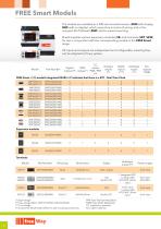
The models are available as a DIN rail-mounted version (SMD with display, SMC with no display), which saves time in terms of wiring, and in the compact 32x74 Eliwell (SMP) size for panel-mounting. Eliwell supplies various expansion modules (SE) and terminals (SKP, SKW) for use in conjunction with the corresponding models in the FREE Smart range. All inputs and outputs are independent and configurable, meaning they can be adapted to fit any system. Part Number Digital TRIAC outputs naogue inputs inputs outputs FREE Smart • (/S) models integrated RS485 »/C indicates that there is a RTC - Real Time...
Open the catalog to page 6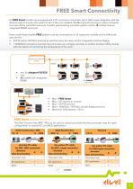
FREE Smart Connectivity All FREE Smart models are equipped with a TTL serial port connection which offers easy integration with the devices used to monitor the system in which they are installed. ModBus standard protocol makes it possible to access all the controller resources, thereby guaranteeing complete system control. /S models have an integrated RS485 serial port. Every model featuring the FREE platform can be connected to an SE expansion module via the LAN serial port, and to: • SKP10 and/or SKP22(L) terminal to view the menu the menu on the integrated machine display • 1 SKW22(L) terminal...
Open the catalog to page 7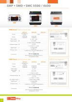
FREE Smart 5500 technical data SMP5500 SMD5500 SMC5500 5500 wiring diagrams Format Power supply Digital outputs 5 2 x Open Collector PPM/PWM 2 x0-10V /S RS485 models only LAN connection to SKP/SKW terminal or SE expansion module FREE Smart 4600 technical data SMP4600 SMD4600 SMC4600 4600 wiring diagrams Format Relay digital outputs 1 x TRIAC 2A 230V Analogue outputs 6 2 x Open Collector PPM/PWM 2 x 0-10V O.C. digital outputs 1 Digital inputs 6 1 x 4..20mA / 0.20mA 1 x Open Collector PWM 6 voltage FREE /S RS485 models only LAN connection to SKP/SKW terminal or SE expansion module
Open the catalog to page 8
FREE Smart 3600 technical data Format Display Power supply Relay digital outputs Analogue outputs 1 x Open Collector PPM/PWM Digital inputs Analogue inputs Expansion module wiring diagrams - /S models with RS485 only LAN connection to SKP/SKW terminal or SE expansion module 4 Expansion module technical specifications Supply Supply Supply Power supply Relay digital outputs Analogue outputs 2 x Open Collector PPM/PWM Digital inputs LAN connection to SKP/SKW terminal or SE expansio
Open the catalog to page 9
Interfaces • FREE Smart terminals FREE Smart terminal technical data SKP10 Format (LxhxD) Front protection Power supply From base From base Analogue inputs From base From base From base Cable COLV000133200 Included in the package Cable COLV000033200 included in the package LAN connection to FREE Smart Cable COLV000033200 included in the package Humidity module optional Cable COLV000033200 included in the package Cable COLV000033200 included in the package Wiring diagrams black / GND blue / signal red /+12Vdc Remote Probe Digital input red /+12Vdc blue / signal black / GND possibilità di alimentare...
Open the catalog to page 10
FREE Smart Mounting SMP • SKP10 Panel-mounted installation. Drill a 29x71 mm hole and insert the instrument; secure it with the special brackets provided. SMC • SMD DIN rail installation See mounting of EVD • EVC • EVE SKP22/SKP22L See EVK mounting page 16 SKW22 • SKW22L • (a) Screw connector for connection to FREE Smart. • (a) JST 3-way connector for connection to FREE Smart. The connector is inside the front keypad which is accessed by removing the cover (use a screwdriver or similar). The cables must pass through the hole in the centre of the rear. Make sure that power supply is of the correct...
Open the catalog to page 11All ELIWELL catalogs and technical brochures
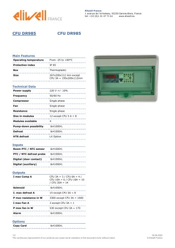 CFU DR985
2 Pages
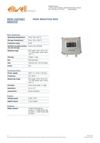 MINI NEGATIVE BOX
1 Page
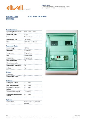 CHT Box DR 4020
2 Pages
 HT800LX
2 Pages
 RC500 NT AIR
2 Pages
 RC 5030
1 Page
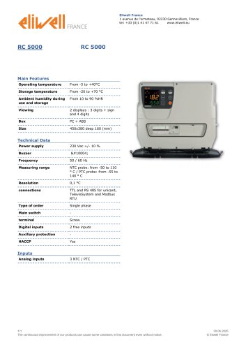 RC 5000
1 Page
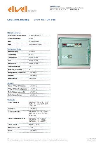 CFUT RVT DR 985
2 Pages
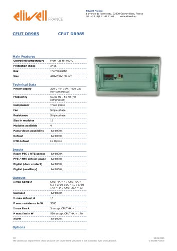 CFUT DR985
2 Pages
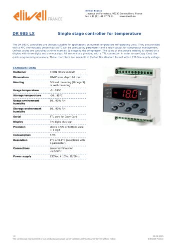 DR 985 LX
2 Pages
 DR 985
2 Pages
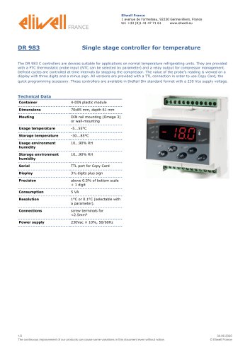 DR 983
2 Pages
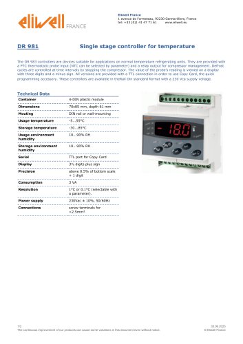 DR 981
2 Pages
 ID 985
2 Pages
 ID 983
2 Pages
 ID 975
2 Pages
 ID 971
1 Page
 ID 970
2 Pages
 ID 961
2 Pages
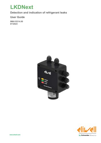 LKDNext
59 Pages

- Temperature probe
- LCD display panel
- Data logger
- Digital temperature control
- Digital indicator
- Pressure switch
- Panel panel meter
- USB datalogger
- Waterproof temperature sensor
- Temperature controller
- Programmable logic controller
- Digital temperature controller
- Leak monitor
- Fuse box
- Illuminated indicator
- LED indicator
- Compact temperature probe
- Gas leak detector
- Ethernet programmable logic controller