Programmable controller Installation manual
1 /58Pages

Programmable controller Installation manual
1 /58Pages
Catalog excerpts

Evolution Programmable controller Installation manual Cont rols
Open the catalog to page 1
Invensys Controls An Invensys Company
Open the catalog to page 2
To allow quick, easy reference, the manual has been designed with the following features: References References column: A column to the left of the text contains references to subjects discussed in the text to help you locate the information you need quickly and easily. Cross references Cross references: All words in italics are listed in the analytical index with the number of the page where they are dealt with in more detail. In the "online" (computer) manual, the words in italics are "hyperlinks" (i.e. mouse-clickable links), connecting up the different parts of the manual and making it "navigable"....
Open the catalog to page 4
1.1.1 Specifications: FREE Evolution EVD / EVC has 27 inputs/outputs, 5 of which are analogue outputs, 6 analogue inputs, 7 relay digital outputs (or 5 relays + 2 SSRs) and 9 digital inputs. FREE Evolution EVD / EVC comes in two different models, allowing you to choose an integrated serial as standard with or without integrated USB as standard (/U model). FREE Evolution EVD comes with a built-in graphics user terminal whilst FREE Evolution EVC has no display, to be connected to a remote EVK graphics terminal for the configuration of BIOS parameters. FREE Evolution is expandable, up to 12 extra...
Open the catalog to page 5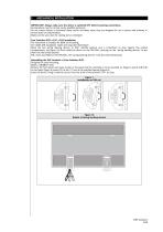
MECHANICAL INSTALLATION IMPORTANT! Always make sure the device is switched OFF before touching connections. All operations must be carried out by qualified personnel. Do not mount devices in extremely damp and/or dirt-laden areas; they are designed for use in places with ordinary or normal levels of contamination. Make sure the area near the cooling slots is ventilated. Free Evolution EVD ● EVC ● EVE Installation The instrument is intended for 8DIN rail mounting. For GUIDA DIN installation, follow the steps described below: Move the two spring docking devices to their standby position (use a...
Open the catalog to page 6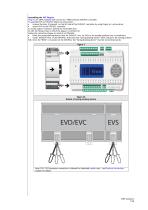
Assembling the EVS Plug-ins Plug-ins are 2DIN modules that connect to a FREE Evolution EVD/EVC controller. To assemble EVS to EVD/EVC follow the instructions: remove the door (if present) on the left side of the EVD/EVC controller by using fingers or a screw-driver anchor EVS to the EVD/EVC controller a) via the plug-in connector, behind the removable door. b) with the fixing screws to which the plug-in is anchored to Follow the instructions below to install it on DIN RAIL: Move the spring docking devices (two for EVD/EVC, one for EVS) to his standby position (use a screwdriver). Install...
Open the catalog to page 7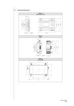
Mechanical dimensions Figure 4 EVD ● EVC ● EVE
Open the catalog to page 8
ELECTRICAL CONNECTIONS General warnings Before doing anything, make sure the device is connected to a suitable external transformer. The following rules must be followed when connecting cards to each other and to the application: Loads that exceed the maximum limits set forth herein must not be applied to outputs. When connecting loads, follow connection diagrams carefully. To avoid electric pairings, wire all low SELV (*) utilities separately from high voltage ones. IMPORTANT! Make sure the machine is switched off before working on the electrical connections. All operations must be carried...
Open the catalog to page 9
3.1.3 Serial connections • All models have an integrated CAN serial as standard. • 7500 models have an integrated RS485 serial as standard. • 75MP models have an integrated MPBUS serial as standard. • /U models have an integrated USB serial as standard. PAY ATTENTION WHILE CONNECTING SERIAL LINES: DO NOT CABLE RS485_N_CAN PORT OR VICEVERSA By means of the EVS plug-in modules, further serial ports are available for integration with industrial, BMS and Ethernet systems. The controller serial ports are defined as 'OnBoard' (OB), whereas the serial ports available on the EVS modules are identified...
Open the catalog to page 10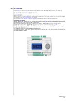
On /U models only On /U models only there are 22 USB connectors inside the door on the right of the LEDs, on the top part of the cap. N.B.: the two USBs should not be used at the same time. Type A USB (HOST) Used to connect a standard USB directly to download the application. This should be done from the controller keypad (EVD model) or from an EVK1000 terminal (EVC model). See the section on User Interface / USB-Host Handling for handling files stored on the USB memory stick Type B mini USB (DEVICE) Used to connect FREE Evolution to a PC or third party device via mini USB cable to up/download...
Open the catalog to page 11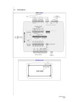
Wiring diagrams 7500(/U) Models DIGITAL INPUTS 24 Va/c 48 Vc + EVC/EVE models PLUG-IN Connector ANALOGUE OUTPUTS FAST DIGITAL INPUT AO1 G AO2 G AO3 G DIGITAL OUTPUTS
Open the catalog to page 12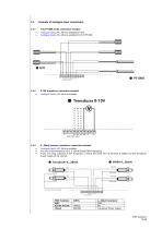
3.3 Example of analogue input connections 3.3.1 NTC/PT1000 probe connection example • Analogue inputs AI1...AI6 are available for NTC. • Analogue inputs AI3...AI6 are available for NTC/PT1000. 3.3.2 0-10V transducer connection example • Analogue Inputs AI3...AI6 are available. 3.3.3 4...20mA pressure transducer connection example • Analogue Inputs AI3...AI6 are available. • You are recommended to use a 4.20mA Eliwell EWPA transducer. • If you are using a general 3-wire transducer, connect the earth wire to terminal G (GND) and the transducer power supply to the 12Vout. # Transducer 4...20mA #...
Open the catalog to page 14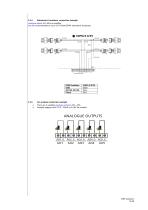
Analogue Inputs AI3...AI6 are available. You are recommended to use a 0-5V Eliwell EWPA ratiometric transducer.
Open the catalog to page 15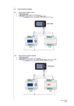
3.4 Serial connection examples 3.4.1 CAN connection example 1 (Field) • 1 FREE Evolution EVE expansion connected in CAN • 1 EVK1000 terminal connected in CAN to FREE Evolution EVD o The EVK1000 terminal is supplied by EVD via the POWER OUT output. 3.4.2 CAN connection example 2 (Network) • 1 FREE Evolution EVC connected in CAN (binding) • 1 EVK1000 terminal connected in CAN to FREE Evolution EVD or, alternatively, to EVC o The EVK1000 terminal is supplied by EVD via the POWER OUT output.
Open the catalog to page 16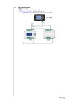
RS485 connection example 1 FREE Evolution EVD 1 FREE Evolution EVE expansion connected in RS485 1 EVK1000 terminal connected in CAN to FREE Evolution EVD o The EVK1000 terminal is supplied by EVD via the POWER OUT output.
Open the catalog to page 17All ELIWELL catalogs and technical brochures
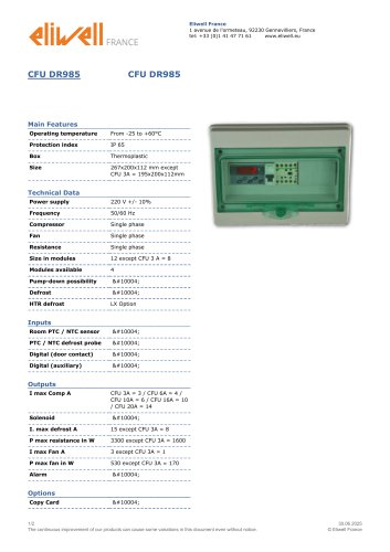 CFU DR985
2 Pages
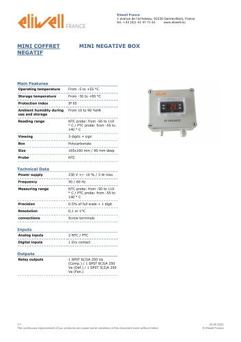 MINI NEGATIVE BOX
1 Page
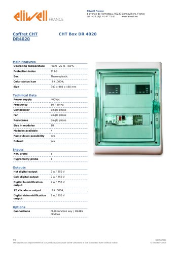 CHT Box DR 4020
2 Pages
 HT800LX
2 Pages
 RC500 NT AIR
2 Pages
 RC 5030
1 Page
 RC 5000
1 Page
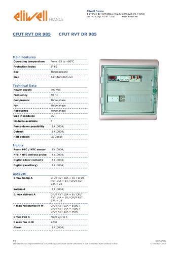 CFUT RVT DR 985
2 Pages
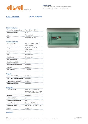 CFUT DR985
2 Pages
 DR 985 LX
2 Pages
 DR 985
2 Pages
 DR 983
2 Pages
 DR 981
2 Pages
 ID 985
2 Pages
 ID 983
2 Pages
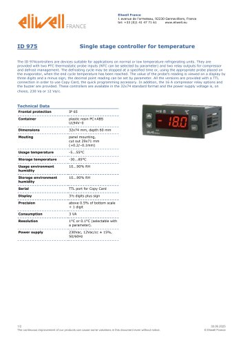 ID 975
2 Pages
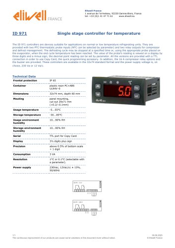 ID 971
1 Page
 ID 970
2 Pages
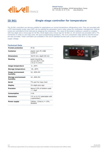 ID 961
2 Pages
 Programmable controllers
20 Pages
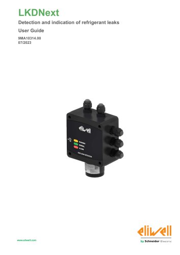 LKDNext
59 Pages
- Temperature probe
- LCD display panel
- Data logger
- Digital temperature control
- Digital indicator
- Pressure switch
- Panel panel meter
- USB datalogger
- Waterproof temperature sensor
- Temperature controller
- Programmable logic controller
- Digital temperature controller
- Leak monitor
- Fuse box
- Illuminated indicator
- LED indicator
- Compact temperature probe
- Gas leak detector
- Ethernet programmable logic controller