

LKDNext
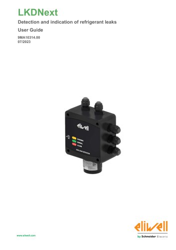
LKDNext
- General Description: The document provides an overview of the LKDNext device, designed for detecting refrigerant leaks.
- Environmental Characteristics: It specifies suitable environmental conditions for the device's operation.
- Disposal: Guidelines for the proper disposal of electrical equipment and sensors are included.
- Preparation: Steps include power disconnection and environmental considerations before installation.
- Mounting: Instructions cover dimensions and positioning for mounting the LKDNext device.
- Location Instructions: Guidance is provided for sensor placement in various environments like equipment rooms and cold rooms.
- Wiring Best Practices: Guidelines for wiring include handling considerations and electrical connections.
- Refrigerant List: A list of compatible refrigerants with the device is provided.
- Device States: The document explains operating states and LED indicators.
- Service Wheel: Descriptions and configurations for the service wheel are included.
- Modbus Settings: Instructions for setting parameters via the Modbus network are provided.
- Alarm Management: Procedures for managing alarms and warnings are detailed.
- Sensor Principles: Operating principles of different sensor types are explained.
- Sensor Replacement: Procedures for replacing sensors are outlined.
- Cleaning: Instructions for cleaning the device are provided.
- Warnings: Important safety warnings and symbols are included to prevent injury.
- Qualified Personnel: Only trained individuals should handle the device.
- Intended Use: The device is intended for commercial HVAC systems and must comply with safety regulations.
- Prohibited Use: Restrictions on improper use and installation are specified.
- Contact details for technical support and sales inquiries are provided.
Before installing the device and its accessories, ensure compliance with all safety indications, electrical requirements, and current legislation. The document emphasizes the necessity of experience in designing and programming automated control systems. It is crucial to ensure that all equipment and systems comply with local, regional, and national regulations and standards to avoid serious injury or equipment damage.
All power must be disconnected from equipment before installation or removal of accessories to prevent electric shock, explosion, or arc flash. Proper voltage sensing devices should be used to confirm power removal, and all covers and connections must be secured before reapplying power.
The device is not designed for use in hazardous locations. Compliance with directives such as "Directive 2014/34/EU ATEX" and "NFPA 70, Hazardous Location" is necessary to prevent potential explosions.
Appropriate safety interlocks should be used where hazards exist. The equipment must be installed in a properly rated enclosure, and power circuits must comply with regulatory requirements. Electrostatic discharge protection is necessary during handling.
The LKDNext devices are intended for wall mounting, with specific instructions for built-in and remote versions. Care must be taken to avoid electrostatic damage. The document provides detailed diagrams and torque specifications for mounting components like cable glands and dongles.
Dimensions for built-in and remote models are provided, along with correct and incorrect mounting positions. Minimum clearances are specified based on refrigerant type, with guidelines for sensor placement in various environments like equipment rooms, cold rooms, and chillers.
There are no general rules for sensor placement; however, guidelines are provided to support installers. Sensors should be placed near high concentrations of refrigerant and mechanical parts, avoiding areas with high-pressure gas to ensure accurate leak detection.
Installation Recommendations: Gas detectors should be installed in areas of greatest risk, such as near air flows from ventilation and heating systems. Since refrigerant gases are denser than air, detectors should be placed close to the floor. Avoid installing detectors under mirrors, washbasins, inside bathrooms, or near steam sources.
The device initiates a start-up cycle upon power connection, consisting of a start-up phase (20 seconds) and a warm-up phase. During start-up, the device's main functions are initialized, and LEDs activate sequentially. The device is not operable during this phase. The warm-up phase adjusts and stabilizes the sensor output signal, allowing gas detection but with less reliable measurements. Calibration is not possible during this phase. The warm-up duration varies by sensor type: Semiconductor and Electrochemical sensors require 5 minutes, while Infrared sensors need 2 minutes. Environmental conditions may extend this period, with full stabilization taking 2 to 24 hours.
The device uses three LEDs (yellow/green/red) to indicate operating status. Various states such as warm-up, normal operation, and alarms are visually represented by these LEDs. The device also includes a service wheel for configuration, with LEDs indicating different parameters like warning levels, alarm levels, and Modbus address.
The service wheel allows basic configuration of the device. It requires a digital multimeter to read voltage values corresponding to selected settings. The wheel is used to set parameters such as warning and alarm thresholds, Modbus address, alarm delay, and analog output type. The configuration process involves selecting parameters, adjusting settings, and saving changes.
The device supports Modbus RTU communication, allowing interaction with a network of devices. Modbus parameters include address, baud rate, stop bit, and parity. The protocol uses a master-slave technique, with the master sending messages and slaves responding. The device's Modbus settings can be configured via an app or the service wheel.
For optimal Modbus network operation, use a shielded 3-wire cable and ensure consistent communication parameters across devices. Maintain a single bus layout, limit connection lengths to 100 meters, and ensure proper signal polarity and grounding. The device's Modbus interface allows access to status messages and parameters via Bluetooth or Modbus controller.
Catalog excerpts
Detection and indication of refrigerant leaks User Guide iWi/iW www.eliweM.com by Schneider Electric
Open the catalog to page 1
Legal Information The Schneider Electric brand and any trademarks of Schneider Electric SE and its subsidiaries referred to in this guide are the property of Schneider Electric SE or its subsidiaries. All other brands may be trademarks of their respective owners. This guide and its content are protected under applicable copyright laws and furnished for informational use only. No part of this guide may be reproduced or transmitted in any form or by any means (electronic, mechanical, photocopying, recording, or otherwise), for any purpose, without the prior written permission of Schneider Electric....
Open the catalog to page 2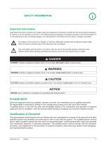
SAFETY INFORMATION Important information Read these instructions carefully and visually inspect the equipment to familiarize yourself with the device before attempting to install it, put it into operation or service it. The following warning messages may appear anywhere in this documentation or on the equipment to warn of potential dangers or to call attention to information that can clarify or simplify a procedure. The addition of this symbol to a ‘Danger’ or ‘Warning’ safety label indicates that an electrical hazard exists which will result in personal injury if the instructions are not followed....
Open the catalog to page 5
Intended use The products described or affected by this document, together with software, accessories, and options, are controllers, intended for commercial HVAC machines according to the instructions, directions, examples, and safety information contained in the present document and other supporting documentation. The product may only be used in compliance with all applicable safety regulations and directives, the specified requirements, and the technical data. Prior to using the product, you must perform a risk assessment in view of the planned application. Based on the results, the appropriate...
Open the catalog to page 6
Install the sensor inside the room at a proper height depending on the refrigerant. Being gases heavier than air, it is normally recommended to position LKDNext sensor lower than the average height of people inside the room. With heavier than air gases such as halocarbon and hydrocarbon refrigerants such as R404A, propane, and butane sensors should be located near ground level. With lighter than air gas for example ammonia, the sensor needs to be located above the equipment to be monitored on a bracket or high on a wall within 300 mm of. With similar density or miscible gases, such as CO2, sensors...
Open the catalog to page 7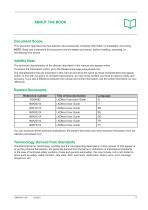
ABOUT THE BOOKDocument Scope This document describes the Gas detector and accessories including information on installation and wiring. NOTE: Read and understand this document and all related documents, before installing, operating, or maintaining your device. The technical characteristics of the devices described in this manual also appear online. To access the information online, go to the Eliwell home page www.eliwell.com The characteristics that are presented in this manual should be the same as those characteristics that appear online. In line with our policy of constant improvement, we...
Open the catalog to page 8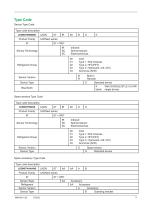
Device Type Code
Open the catalog to page 9
Product Related Information DANGER HAZARD OF ELECTRIC SHOCK, EXPLOSION OR ARC FLASH • Disconnect all power from all equipment including connected devices, prior to removing any covers or doors, or installing or removing any accessories, hardware, cables, or wires. • Always use a properly rated voltage sensing device to confirm the power is removed. • Replace and secure all covers, accessories, hardware, cables, and wires and confirm that a proper ground connection exists before applying power to the unit. • Use only the specified voltage when operating this equipment and any associated products....
Open the catalog to page 13
• Keep equipment in the protective conductive packaging until you are ready to install the equipment. • Only install equipment in approved enclosures and / or locations that prevent casual access and provide electrostatic discharge protection. • Use a conductive wrist strap or equivalent field force protective device attached to an earth ground when handling sensitive equipment. • Always discharge yourself by touching a grounded surface or approved antistatic mat before handling the equipment. Failure to follow these instructions can result in death, serious injury, or equipment damage._ • Use...
Open the catalog to page 14
The LKDNext series leakage detectors continuously monitor indoor air for any refrigerant leaks. The devices can be used for refrigeration applications (cold rooms, freezer rooms, machinery rooms). The LKDNext series detectors are available in the following configurations: • Built-in version • Remote version They are calibrated to detect most refrigerants currently available on the market. The sensitive elements are constructed using semiconductor (SC) technology, infrared (IR) technology, or electrochemical (EC) technology. The LKDNext series detectors can be used in stand-alone applications...
Open the catalog to page 15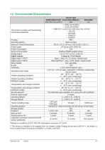
‘Reference conditions at 25°C 50% RH atmospheric pressure 101.3 kPa ** The device is intended to be supplied from an isolated Limited Energy Source per UL61010-1, 3rd edition cl. 9.4 or Limited Power Source per UL60950-1 or Class 2 per NEC
Open the catalog to page 16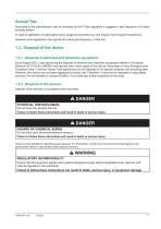
Annual Test According to the manufacturer, and as indicated by the F-Gas regulation it suggests a test frequency of at least annually sensor. In case of application of particularly heavy usage environment you may require more frequent inspections. However local regulations may specify the nature and frequency of this test. 1.3. Disposal of the device 1.3.1. Disposal of electrical and electronic equipment Since August 2012, rules governing the disposal of electrical and electronic equipment defined in European Directive 2012/19/ EU (WEEE) and national laws, which apply to this device, have been...
Open the catalog to page 17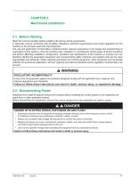
CHAPTER 2 Mechanical installation 2.1. Before Starting Read this manual carefully before installing the device and its accessories. In particular, ensure conformity with all safety indications, electrical requirements and current legislation for the machine or the process used with this equipment. The use and application of information contained herein requires experience in the design and programming of automated control systems. Only the machine user, integrator or manufacturer will be aware of all the conditions and factors affecting installation, configuration, operation and maintenance of...
Open the catalog to page 18All ELIWELL catalogs and technical brochures
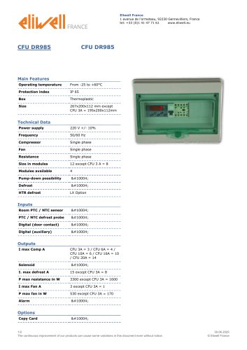 CFU DR985
2 Pages
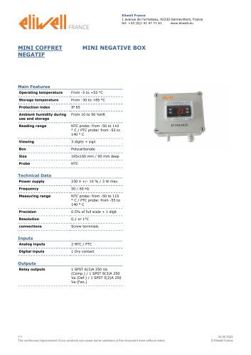 MINI NEGATIVE BOX
1 Page
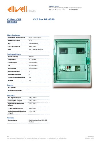 CHT Box DR 4020
2 Pages
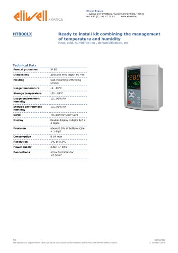 HT800LX
2 Pages
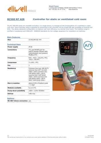 RC500 NT AIR
2 Pages
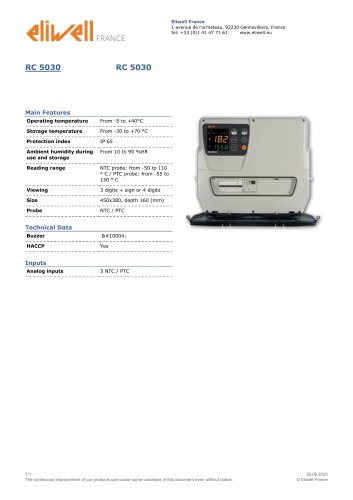 RC 5030
1 Page
 RC 5000
1 Page
 CFUT RVT DR 985
2 Pages
 CFUT DR985
2 Pages
 DR 985 LX
2 Pages
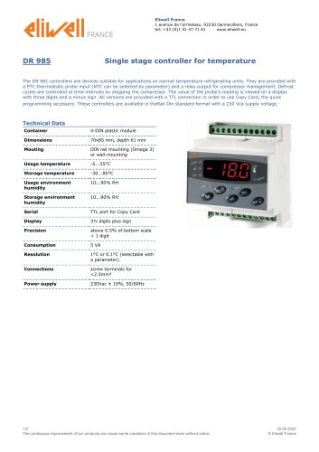 DR 985
2 Pages
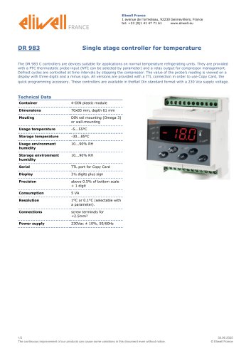 DR 983
2 Pages
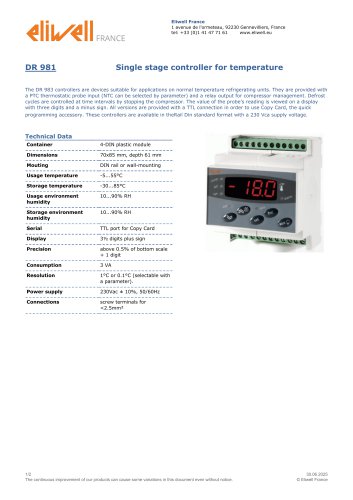 DR 981
2 Pages
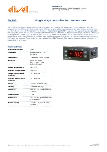 ID 985
2 Pages
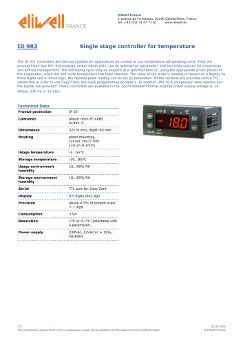 ID 983
2 Pages
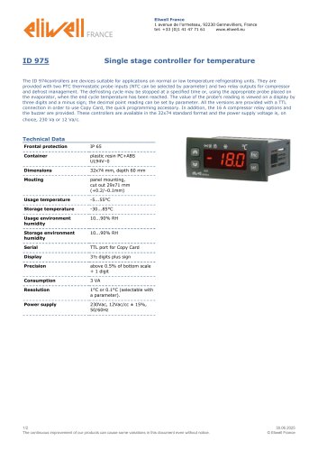 ID 975
2 Pages
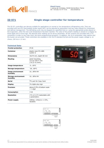 ID 971
1 Page
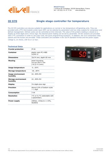 ID 970
2 Pages
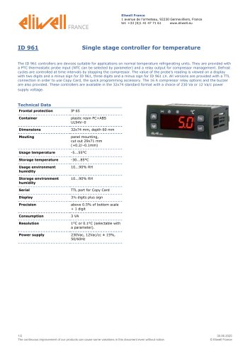 ID 961
2 Pages
 Programmable controllers
20 Pages

- Display module
- Temperature probe
- LCD display panel
- Data logger
- Digital temperature control
- Digital indicator
- Pressure switch
- Panel panel meter
- USB datalogger
- Waterproof temperature sensor
- Temperature controller
- Programmable logic controller
- Digital temperature controller
- Leak monitor
- Fuse box
- Illuminated indicator
- Compact temperature probe
- Ethernet programmable logic controller
- Temperature indicator