
- Catalogs
- Elite Line Industrial Corp.
- BTS / BFS

BTS / BFS

BTS / BFS
- The controller is directly fixed and designed without a conduit, reducing potential damage during transport.
- Quick screw fastening allows for easy installation.
- The valve body is compatible with all controller types without technical conversion, forming various control valves.
- The cylinder design supports both low and high pressure in vertical and horizontal positions.
- A straight flow path minimizes malfunctions from impure water and reduces turbulence.
- The valve body is compact, lightweight, and easy to install, with a simple and elegant appearance.
- Manufactured by professionals, ensuring high quality and reasonable pricing.
- Patent Number: 135517
- Applied Conditions: Fluid & Air
- Temperature Range: -15° to 80°C
- Connection Ends: Compatible with all international standards
- Materials: Cast Iron, Ductile Iron, Bronze, Stainless Steel
The valve operates through an inlet-guiding hole that transfers pressure to a pressure chamber. Accumulated pressure pushes the piston to close the valve seat. An outlet guiding hole allows pressure dissipation, enabling the valve to open under incoming water pressure.
- Used in pipe installations to maintain minimum working pressure and balance upstream and downstream pressure.
- Ensures constant pressure during normal and emergency conditions.
- Pressure Adjusting Range: 0.3 to 4 kgf/cm² (1 kgf/cm² = 14.2 psi)
- Working pressure must exceed 0.3 kgf/cm², with full gate opening at 1.5 kgf/cm².
- Production Size Range: 1.5” to 56”
- Flow rate chart provided for various sizes and configurations.
Catalog excerpts

MULTI-FUNCTION AUTO-CONTROL VALVE » Controller is fixed directly and designed of non-controller conduit. It reduces the damage of the controller conduit while transporting the equipment. > Controller is designed to be quickly screw fastened, enabling fast and easy installation. » The valve body can match with all types of controller without technical conversion, and all kinds of control valves can be formed. » Cylinder design is adopted for the valve body structure, making the valve applicable to low and high pressure in both vertical and horizontal positions. > Straight flow path is designed inside valve body. The large flow can reduce the malfunctions caused by impure water and effectively decrease turbulence and related bad effects. » The valve body is shaped and formed as whole. Small volume, lightweight, and easy installation. Simple and elegant appearance. > Professional manufacturers, best quality, and reasonable price. Outlet guiding hole ? Z (Controller inlet hole) hole Pressure chamber Controller outlet Cylinder bolt O-ring Cylinder Spring U-ring Piston Seat Shaft Inlet guiding hole » Patent Number 1. Applied conditions: Fluid & Air 2. Applied temperature: -15° ~ 80°C 3.Connection ends: Available for all international standards 4. Materials of valve body: Cast Iron, Ductile Iron, Bronze & Stainless Steel The valve body of main valve becomes functional by an inlet-guiding hole. This hole transfers pressure to pressure chamber. When enough pressure accumulates in the pressure chamber, it generates pushing force that makes the piston close to valve seat and generates the closing motion. There is another outlet guiding hole inside the pressure chamber. When the hole is open, pressure in pressure chamber dissipates and valve pate is pushed open by incoming water pressure. Working Pressure Cast [ron Cast Iron Test Pressure Cast Iron
Open the catalog to page 1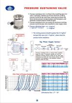
» Pressure sustaining valve is utilized when installing pipes for users. It primarily matches up with the minimum working pressure inside the tap water pipe, balancing up-stream and down-stream pressure during normalcy and emergency, and maintains constant pressure inside the pipe. > Pressure sustaining valve can sustain the maximum working pressure inside the pipe when installed in water supply areas. » Pressure adjusting range : (,3~4 kgf/cm’ (1kgf/cm™=14.2 psi) 2~8 kgf/cm” » The working pressure should be greater than 0.3 kgf/cm’ and gate fully open with 1.5 kgf/cm?®, please check the pilot...
Open the catalog to page 2All Elite Line Industrial Corp. catalogs and technical brochures
 Float Valve Switch
1 Page
 HRT
HRT1 Page
 CHF
CHF2 Pages
 ATR
ATR1 Page
 FVT
FVT1 Page
 DTE
DTE1 Page
 RPF
RPF1 Page
 DTR
DTR1 Page
 DTF
DTF1 Page
 RAF
RAF1 Page
 AXT
AXT1 Page
 AIT
AIT1 Page
 RLT
RLT1 Page
 HSU
HSU1 Page
 HSK
HSK1 Page
 HST
HST1 Page
 HSY
HSY1 Page
 HSR
HSR1 Page
 HSD
HSD1 Page
 HSL
HSL1 Page
 HSM
HSM1 Page
 HWD
HWD1 Page
 HAG
HAG1 Page
 HRA
HRA1 Page
 HHY
HHY1 Page
 HTD
HTD1 Page
 HBS
HBS1 Page
 HCV-350GG
1 Page
 HCV-300FF
1 Page
 HGO-200GG
1 Page
 HGO-300FF
1 Page
 HGN-300FF
1 Page
 HBF-300W
1 Page
 HBF-300G
1 Page
 UL-BFR
1 Page
 BFL-F
BFL-F1 Page
 BFE
BFE1 Page
 BFE
BFE2 Pages
 BTL / BFL
2 Pages
 BTR/BFR
2 Pages
 BGR
BGR1 Page
 RS
RS2 Pages
 RDST
RDST1 Page
 RDT
RDT1 Page
 Pressure Relief valve
1 Page
 Pressure Reducing Valve
1 Page
 Float valve
1 Page
 Pump control valve
2 Pages


Archived catalogs
 SOLENOID CONTROL VALVE
1 Page

- Elite Line manual valve
- Elite Line stainless steel valve
- Elite Line water valve
- Ball valve
- Elite Line threaded valve
- Electrically operated valve
- Elite Line regulating valve
- Elite Line flange valve
- On/off valve
- Flap valve
- Check valve
- Electric valve
- Lever valve
- ISO valve
- 2-way solenoid valve
- NC solenoid valve
- Elite Line pressure regulator
- Gas valve