- Catalogs
- Elfa Group
- Operator Joystick
- Company
- Products
- Catalogs
- News & Trends
- Exhibitions
Operator Joystick
1 /10Pages

Operator Joystick
1 /10Pages
Catalog excerpts
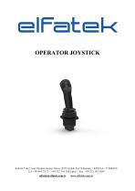
OPERATOR JOYSTICK
Open the catalog to page 1
1. About Us Elfatek Elektronik, which was established in 2006 and became the leader in its sector in a short time, is an R&D company that exports its products to the whole world, especially Turkey, with its domestic production and domestic capital. Elfatek has succeeded in producing Turkey's first crane remote control with 80 channels and a working time of more than 240 hours in this sector, where it has stepped in with the production of crane controls. As of 27.10.2017, it was registered as the 1st R&D center in Konya in the Industrial Electricity Sector and the 41st R&D center throughout Turkey...
Open the catalog to page 2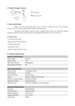
2. Product Package Contents 1 User Manual 3. Main Specifications Thanks to the non-contacting hall effects sensors, it offers a 5 million life cycle. It has CANopen, CANJ1939, and CAN Freestyle outputs and is compatible with many devices. The presence of the operator’s hand is sensed by a capacitive sensor. With visual, audible, and vibrating notifications it offers maximum safety and ergonomy. Included RFID reader allows you to track operators. 4. Usage Areas - Crane and Lifting Systems - Agricultural and Forestry Machinery - Construction Machinery - Municipality Vehicles - Mobile On-Board Hydraulic...
Open the catalog to page 3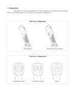
7. Configurations Placements of the buttons and thumbwheels are fully customizable on the front and back face plates. There are some example designs as you can design your configuration and placements. Back Face Configuration Without Buttons With Rocker Switch and Button Front Face Configurations
Open the catalog to page 5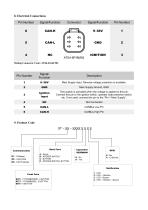
8. Electrical Connections Pin Number Mating Connector Code: AT06-6S-KIT01 Signal/ Function Main Supply Input. Reverse voltage protection is available. Main Supply Ground, GND Ignition Input The joystick is activated when the voltage is applied to this pin. Connect this pin to the ignition switch, operator seat presence switch, etc. If not used, connect this pin to the “Pin-1 Main Supply”. 9. Product Code ST – XX – XXXX X X X X Back Face Communication C1 - CANopen C2 - CANJ1939 C2 - CAN Freestyle A - Empty B - ROCKER SWITCH C - BUTTON D - ROCKER SWITCH, BUTTON Notification Front Face B4T2 - 2...
Open the catalog to page 6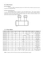
10. CANBus Protocol 10.1 Pin Assignment To use the CANBus communication protocol, the CANH and CANL terminals on the device must be connected to the communication line. 10.2 Bus Termination Resistance Bus termination resistors are required to work with CANBus protocol. These resistors should be connected to the line at both ends with a 120Ω value. When the line setup is ready, equal line resistance should be around 60Ω. The device has internal software termination resistance also. Which is activated by default. Can be deactivated/activated from register address “0x6030”. Grip Temp Joystick Analog...
Open the catalog to page 7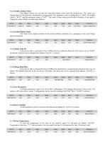
11.1 Joystick Analog Values The address where you can read the measured analog values from the joystick axis. The values can change based on the front-face thumbwheel configurations. The minimum value of analog data is “0x00”, the middle value is “0x7F”, and the maximum value is “0xFF”. The order of these values given below is default, if you need to change the order of them, use these byte indexes. CAN ID Grip Temp Joystick Analog Values 11.2 Joystick Digital Values The values of the digital elements on the joystick (Button, deadman, etc.), emergency value, and 5-stage speed information. CAN...
Open the catalog to page 8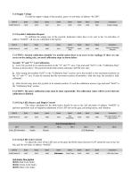
11.8 Supply Voltage To read the supply voltage of the joystick, query 1st sub-index of address “0x2109”. CAN ID Supply Voltage 11.9 Joystick Calibration Request To calibrate the analog axis of the joystick, dedicated values have to be sent to the 1st sub-index of address “0x6020”. All axis are calibrated at the factory. CAN ID Calibration Step Joystick Calibration Request CAUTION: Joystick calibration shouldn’t be needed unless there is an error in the readings. If there are any errors on the analog axis, you need calibration steps as shown below. Joystick “X” and “Y” Axis Calibration 1- Leave...
Open the catalog to page 9
11.12 CANBus Termination Activation The termination resistor, which must be present in the CANBus line, is built into the joystick. This resistor can be activated by software. The preferred setting should be sent to sub-index 1 of address “0x6030”. It is activated by default. CAN ID 0x600+Node ID CANBus Termination Activation 11.13 Change Analog Value Order The data order on the "0x180", where the values of the analog elements on the joystick are sent, can be changed. The 4th byte part of the address “0x6060”, the built-in sequence number of the analog data to be replaced, and the 5th byte part...
Open the catalog to page 10All Elfa Group catalogs and technical brochures
 Delocan Transmetteur
2 Pages
 Angle limit sensor
1 Page
 En-Q remote control
2 Pages
 Kugu remote control
2 Pages
 Turna remote control
2 Pages
 En-Mid remote control
32 Pages
 N LIGHT & TOWER LIGHT
8 Pages
 Elevator and crâne industry
2 Pages
 Remote Display
2 Pages
 Mobile Radio Remote Control
8 Pages


- Industrial press
- Bourn And Koch display
- Hydraulic press
- Warning light
- Wireless remote control
- LED display panel
- Industrial remote control
- Remote control with buttons
- Joining press
- Tilt sensor
- LED beacon light
- Bourn And Koch electronic display
- DC beacon light
- Strobe warning light
- Pneumatic press
- IP65 remote control
- CNC router
- 24VDC warning light
- AC warning light
- Bourn And Koch drilling machine